Water drainage and dynamic compaction all-in-one device and use method thereof

An integrated, rammer technology, applied in soil protection, construction, infrastructure engineering, etc., can solve problems such as hindering ramming, small force area of ​​rammer, and inconspicuous effect, so as to accelerate the dissipation of pressure and improve the structure of the device Simple, wide-ranging effects

Active Publication Date: 2016-12-07
海盈生态环境研究院(南京)有限公司
View PDF7 Cites 8 Cited by
  • Summary
  • Abstract
  • Description
  • Claims
  • Application Information

AI Technical Summary

Problems solved by technology

However, in the actual application of dynamic compaction, there are the following shortcomings to be solved: First, because the construction soil is relatively soft, when the tamper hammer is smashed into the soft clay, it will sink into the soil, and the air in the surrounding soil will be squeezed out After that, it will form a vacuum adsorption on the rammer, making it difficult to pull out the rammer; second, the force-bearing area of ​​the rammer is relatively small, and it will generate a large pressure when it contacts with the soil, which will make the stress and force of the soil The settlement distribution is uneven. Although there is a bulldozing process in the later stage, the effect is not obvious; third, the rammer falling from a high altitude will have a greater impact on the soil, and the soil will quickly generate high excess pore water pressure. At the same time, the water level will also rapidly increase. These will hinder the next tamping; usually it takes 3-5 days for the excess pore water pressure to dissipate after a strong tamping, which greatly slows down the construction progress and is not conducive to the rapid reinforcement of the soil; Ramming is a dynamic consolidation method, which will generate huge noise during operation, so the application place and time of dynamic compaction are greatly limited
These shortcomings seriously limit the further development of the dynamic compaction process, but have not been resolved for a long time

Method used


Image

  • Water drainage and dynamic compaction all-in-one device and use method thereof

Examples


Embodiment Construction

[0028] Below in conjunction with embodiment the present invention will be further described.

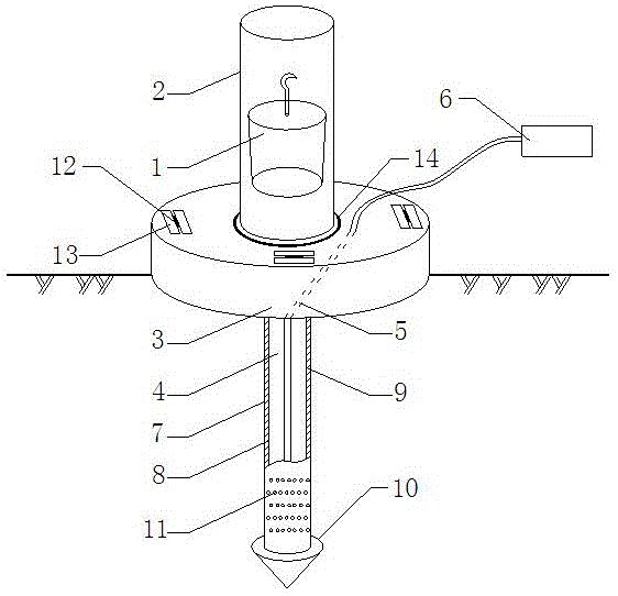
[0029] Such as figure 1 As shown, an integrated device for dewatering and dynamic ramming includes a rammer 1, a muffler sleeve 2, a ramming cap 3, a metal filter tube 4, a drainage hose 5 and a pump 6, and the ramming cap 3 is flat and solid Rigid cylinder, its diameter is 2-3 times of the diameter of tamper 1, and its thickness is 15~25cm;

[0030] The top of the ramming platform 3 is provided with a track groove 14, the track groove 14 and the ramming platform 3 are concentric circles, and the inner rotation of the track groove 14 is embedded with a sound-absorbing sleeve 2. The muffler sleeve 2 is a hollow steel cylinder whose height is freely adjusted by the lifting height of the rammer 1, and whose diameter is 1.2-1.5 times the diameter of the rammer 1, and the rammer 1 is arranged inside the muffler sleeve 2;

[0031] Around the periphery of the track groove 14 and on the up...


PUM


Abstract

The invention discloses a water drainage and dynamic compaction all-in-one device and a use method thereof. The device comprises a rammer, a silencing sleeve, a compaction bearing platform, a metal filter pipe and a water drainage hose, wherein an orbital groove is formed in the top of the compaction bearing platform; the silencing sleeve is mounted in the orbital groove; the rammer is arranged in the silencing sleeve; the lower bottom surface of the compaction bearing platform is connected with the metal filter pipe through a connection opening; the metal filter pipe is a double-layer rigid sleeve; and the double-layer rigid sleeve comprises an inner-layer filter pipe and an outer-layer filter pipe which are arranged inside and outside in a sleeving manner. By the adoption of the compaction bearing platform mode, under a condition of the same compaction energy, the stress on a soil body is more uniform, and the actuating range is wider; the rigid compaction bearing platform serving as a contact surface of the rammer avoids direct contact between the rammer and the soil body in the conventional dynamic compaction process, so that the difficulty that the rammer is hard to pull up after falling to the ground is solved; and due to the synchronous operation of dynamic compaction and water drainage below the center of a compaction point, dissipation of excess pore water pressure in the soil body can be accelerated, and the progress of the engineering is greatly shortened.

Description

technical field [0001] The invention belongs to the technical field of soft soil foundation treatment, and in particular relates to an integrated device for precipitation and dynamic compaction and a use method thereof. Background technique [0002] In the field of soft soil foundation treatment technology, dynamic compaction technology has been widely used in foundation reinforcement projects such as highways, railways, airports, and port reclamation. During the construction process, the rammer is hoisted high, and then the rammer is released to rapidly increase the bearing capacity and compression modulus of the foundation. However, in the actual application of dynamic compaction, there are the following shortcomings to be solved: First, because the construction soil is relatively soft, when the tamper hammer is smashed into the soft clay, it will sink into the soil, and the air in the surrounding soil will be squeezed out After that, it will form a vacuum adsorption on t...

Claims


Application Information

Patent Timeline
Patent Type & Authority Applications(China)
IPC IPC(8): E02D3/10E02D3/046
CPCE02D3/046E02D3/10E02D2200/1685E02D2300/0026
Inventor 李平赖建英陈育民唐建辉王志远刘伟
Owner 海盈生态环境研究院(南京)有限公司
Why Eureka
Try Eureka