Supercharge Your Innovation With Domain-Expert AI Agents!

Water-saving valve with water purification effect

A water-saving valve and function technology, applied in the field of water flow diverter valve, can solve the problems of high cost, secondary pollution of secondary water, easy blockage, etc., and achieve the effect of slowing down time and simple and convenient cleaning.

Inactive Publication Date: 2016-12-07
SICHUAN SKSAS HIGH TECH CO LTD
View PDF9 Cites 0 Cited by
  • Summary
  • Abstract
  • Description
  • Claims
  • Application Information

AI Technical Summary

Problems solved by technology

Urban apartments are a part that must be guaranteed for urban water use, but they also consume a large amount of water. The disadvantages of some current water reuse devices are that the cost is too high or the structure is complicated, which is not conducive to widespread promotion. At the same time, the existing devices Lack of secondary treatment for reused water, secondary water is prone to secondary pollution and existing devices are prone to clogging during use

Method used


Image

  • Water-saving valve with water purification effect
  • Water-saving valve with water purification effect

Examples


Embodiment 1

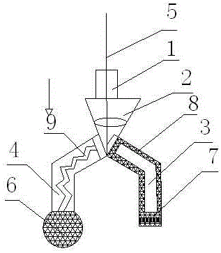
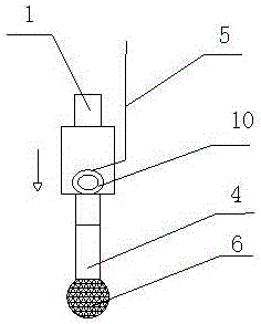
[0021] Such as Figure 1-2 As shown, the present invention includes a water-saving valve with a water purification effect, including a diversion water-saving valve body 2 and a water inlet 1, and the water inlet 1 is installed on the top of the diversion water-saving valve body 1, and also includes an annular permeation tank 8 and a water inlet 1. Spiral strip 9, water outlet a3 and water outlet b4 are set at the bottom of the valve body 2 of the diversion water-saving valve, and a diversion lever 5 is vertically inserted into the body 2 of the diversion water-saving valve, and the lower end of the diversion lever 5 is installed with A splitter that matches the water outlet a3 and the water outlet b4; a filter structure 7 is also set at the outlet of the water outlet a3, and the annular permeation tank 8 is installed on the inner wall of the water outlet a3; a spherical shape is also set at the outlet of the water outlet b4 The filter cover 6 is also equipped with a spiral str...

Embodiment 2

[0025] This embodiment is preferably as follows on the basis of Embodiment 1: the spiral strip 9 extends from the outlet of the valve body 2 of the diverter water saving valve to the top of the filter housing 6 . Maximize the delay of time for sewage to enter the filter housing.

[0026] The moisture in the valve body 2 of the diverting water saving valve can flow into the annular permeation groove 8 . Cleaning agent can be put into the water outlet a for cleaning without additionally setting an opening.

[0027] The filter structure 7 includes three layers, which are upper and lower filter screens and a disinfection layer between the two filter screens.

[0028] The part where the water outlet a3 and the water outlet b4 are in contact with the diverter sheet is a magnetic sheet 10 made of magnetic material. It is convenient for the diverter to switch back and forth between the water outlet a3 and the water outlet b4.

[0029] Multiple bags of solid disinfectant are evenly ...


PUM


Abstract

The invention discloses a water-saving valve with a water purification effect. The water-saving valve comprises a flow distributing water-saving valve body and a water inlet. The water inlet is installed in the top of the flow distributing water-saving valve body. The water-saving valve further comprises an annular permeation groove and a spiral strip. The bottom of the flow distributing water-saving valve body is provided with a water outlet a and a water outlet b. A flow distributing poke rod is further vertically inserted in the flow distributing water-saving valve body. A flow distributing piece matched with the water outlet a and the water outlet b is installed at the lower end of the flow distributing poke rod. A filter structure is further arranged at an outlet body of the water outlet a. The annular permeation groove is installed in the inner wall of the water outlet a. An outlet body of the water outlet b is further sleeved with a spherical filter cover. The spiral strip is further installed in an inner cavity of the water outlet b. According to the water-saving valve with the water purification effect, by means of the structure, classified processing of urban water is achieved, the effect that secondary water is clean is ensured, and in addition, blocking is not prone to occurring in the using process.

Description

technical field [0001] The invention relates to a diverter valve for water flow, in particular to a water-saving valve with water purification function. Background technique [0002] Water is an indispensable resource for human survival. With the rapid increase of urban population, the amount of urban water also increases, but the urban water storage is limited; what is more concerning is that due to the destruction of the earth's ecology, forests With the reduction of area, the deterioration of natural environment, the scarcity of water resources, and the occurrence of drought every year, water use in large and medium-sized cities has become an important thing. Urban apartments are a part that must be guaranteed for urban water use, but they also consume a large amount of water. The disadvantages of some current water reuse devices are that the cost is too high or the structure is complicated, which is not conducive to widespread promotion. At the same time, the existing de...

Claims


Application Information

Patent Timeline
IPC IPC(8): F16K11/02F16K27/00B01D35/02C02F9/04
CPCF16K11/02B01D35/02C02F1/001C02F1/50C02F9/00C02F2303/04F16K27/00
Inventor 张彬
Owner SICHUAN SKSAS HIGH TECH CO LTD
Features
  • R&D
  • Intellectual Property
  • Life Sciences
  • Materials
  • Tech Scout
  • Unparalleled Data Quality
  • Higher Quality Content
  • 60% Fewer Hallucinations
Learn More