Pipeline pressure relief device

A technology for pressure relief devices and pipelines, which is applied to valve devices, pipe components, pipes/pipe joints/pipe fittings, etc., can solve the problems of complicated structure of pipeline pressure relief devices, inability to close pipes in time, and high replacement costs, and achieve easy recovery, Fast pressure relief, good pressure relief performance

Active Publication Date: 2016-12-07
云南国钛金属股份有限公司
View PDF4 Cites 3 Cited by
  • Summary
  • Abstract
  • Description
  • Claims
  • Application Information

AI Technical Summary

Problems solved by technology

[0002] The pipeline pressure relief device in the related art has a complicated structure, is easy to be damaged, and has a high replacement cost. At the same time, the opening of the pipeline cannot be closed in time after the pressure relief, resulting in the leakage of gas in the pipeline and the entry of external gas, and the damage of the pipeline pressure relief device. The structure needs to be improved

Method used


Image

  • Pipeline pressure relief device
  • Pipeline pressure relief device

Examples


Embodiment Construction

[0020] Embodiments of the invention are described in detail below, examples of which are illustrated in the accompanying drawings. The embodiments described below with reference to the accompanying drawings are exemplary, intended to explain the present invention, but not to be construed as limitations of the present invention, those skilled in the art can change the above-mentioned embodiments within the scope of the present invention , modification, substitution and variation.

[0021] The pipeline pressure relief device according to the embodiment of the present invention will be described in detail below with reference to the accompanying drawings.

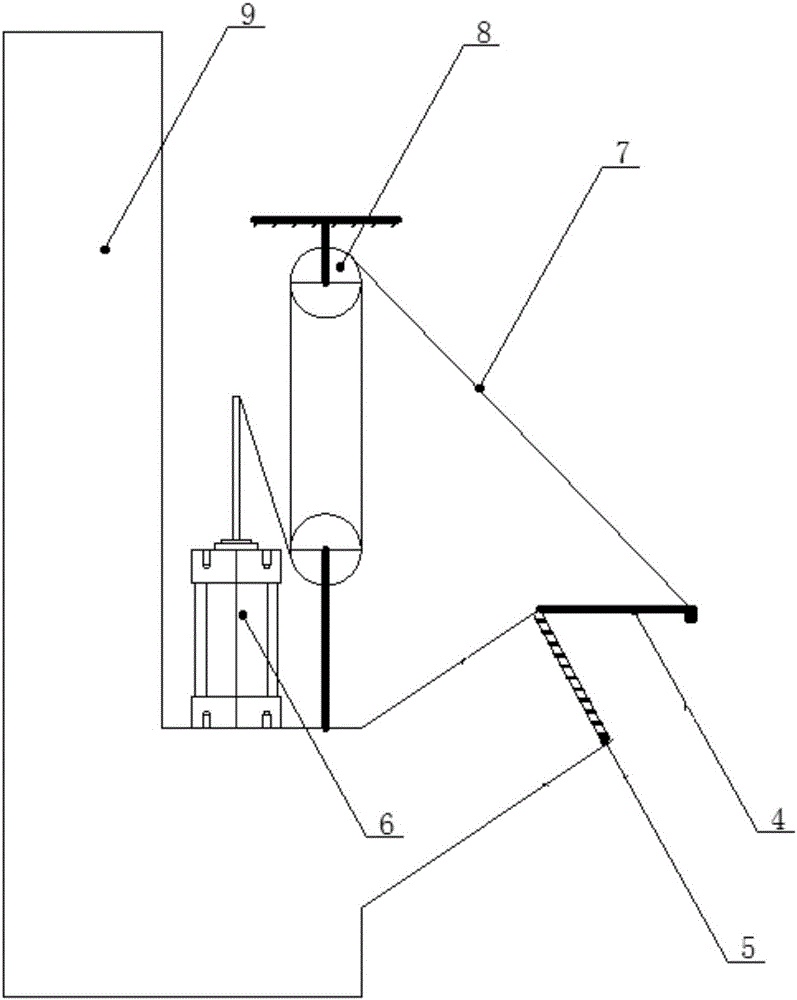
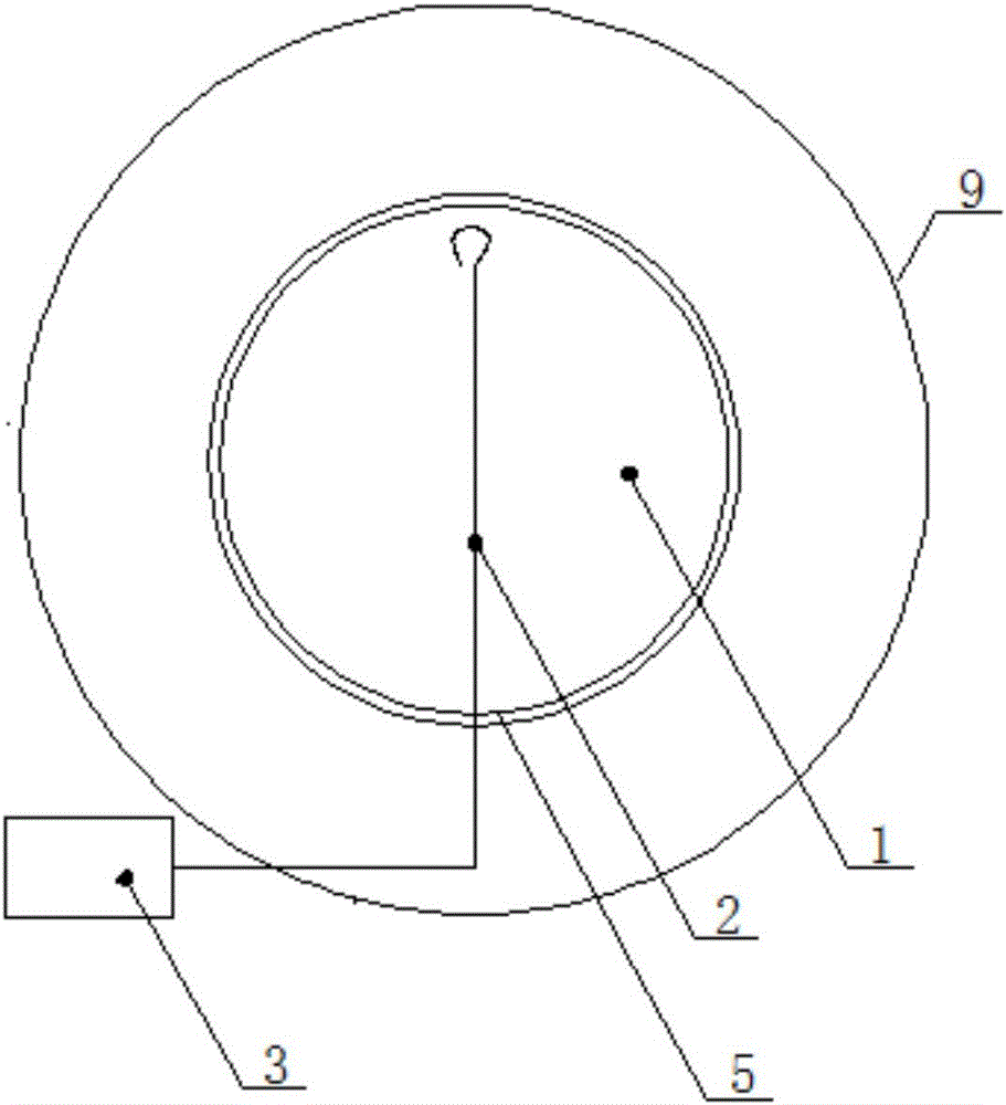
[0022] refer to figure 1 with figure 2 As shown, the pipeline pressure relief device according to the embodiment of the present invention may include an explosion-proof membrane 1 , a signal line 2 , a feedback module 3 , a cylinder 6 and a cover 4 .

[0023] The explosion-proof membrane 1 is sealed at the opening of the p...


PUM


Abstract

The invention discloses a pipeline pressure relief device which comprises an explosion-proof membrane, a signal line, a feedback module, an air cylinder and a sealing cover; the explosion-proof membrane is sealed on an opening of a pipeline; one end of the signal line is arranged on the explosion-proof membrane, and is suitable for being broken when the explosion-proof membrane bursts; the feedback module is connected with the other end of the signal line; the air cylinder is connected with the feedback module; the feedback module is used for enabling the air cylinder to release pressure when the signal line is broken; the sealing cover is positioned above the opening; and the sealing cover is connected with the air cylinder, is pulled by the air cylinder to open the opening, and is moved to close the opening when the air cylinder releases pressure. According to the embodiment of the invention, the pipeline pressure relief device is good in pressure-relief performance, is simple and convenient to recover, is stable in operation, is low in fault rate and is high in safety reliability, can realize quick pressure relief and timely sealing after pressure relief, and quickly and stably guarantees that purified gas in the pipeline does not leaks outside, and outside gas enters.

Description

technical field [0001] The invention relates to a pipeline pressure relief device, which is applicable to poisonous and harmful gas pipelines and clean gas pipelines with strict requirements on air. Background technique [0002] The pipeline pressure relief device in the related art has a complicated structure, is easy to be damaged, and has a high replacement cost. At the same time, the opening of the pipeline cannot be closed in time after the pressure relief, resulting in the leakage of gas in the pipeline and the entry of external gas, and the damage of the pipeline pressure relief device. The structure could be improved. Contents of the invention [0003] The present invention aims to solve one of the technical problems in the related art at least to a certain extent. Therefore, the present invention proposes a pipeline pressure relief device, which has good pressure relief performance, easy recovery, stable operation and low failure rate, and can realize rapid press...

Claims


Application Information

Patent Timeline
Patent Type & Authority Applications(China)
IPC IPC(8): F16K17/16F16L55/115
CPCF16K17/16F16L55/115
Inventor 邹捷李雪刚李波李保金常强田洪位王世武
Owner 云南国钛金属股份有限公司
Why Eureka
Try Eureka