Pressure retaining valve device for pressure fuel tank

A technology of pressure oil tank and pressure maintaining valve, which is applied in the direction of valve device, fuel injection device, lift valve, etc. It can solve the problems of abnormal use, negative pressure and lack of oil and gas leakage, and achieve easy maintenance and use, and simple structure Effect

Inactive Publication Date: 2016-12-07
苏州国雁汽车系统有限公司
View PDF7 Cites 6 Cited by
  • Summary
  • Abstract
  • Description
  • Claims
  • Application Information

AI Technical Summary

Problems solved by technology

[0004] However, there is currently a lack of a control valve to control the flow of fuel gas between the fuel tank and the carbon tank, resulting in the leakage of fuel gas or excessive negative pressure in the implementation, which cannot be used normally

Method used


Image

  • Pressure retaining valve device for pressure fuel tank
  • Pressure retaining valve device for pressure fuel tank
  • Pressure retaining valve device for pressure fuel tank

Examples


Embodiment Construction

[0032] The specific implementation manners of the present invention will be further described in detail below in conjunction with the accompanying drawings and embodiments. The following examples are used to illustrate the present invention, but are not intended to limit the scope of the present invention.

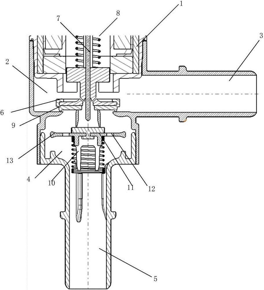
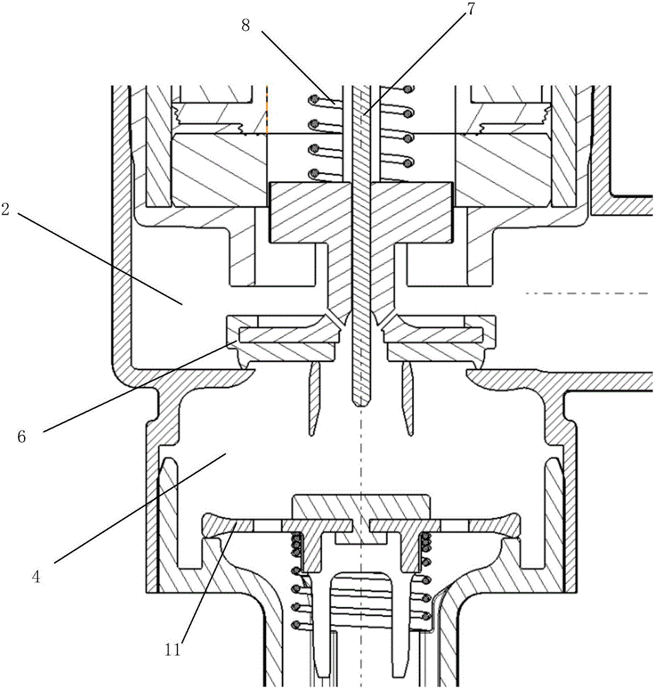
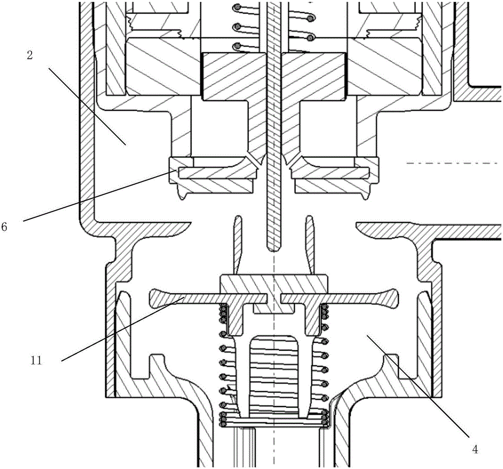
[0033] like Figures 1 to 3 The pressure maintaining valve device for the pressure fuel tank includes a device body 1, which is different in that: the device body 1 is provided with a fuel tank guide chamber 2, and a fuel tank guide chamber 2 is provided on one side of the fuel tank guide chamber 2. Connector 3, and a carbon canister guide chamber 4 is provided below the fuel tank guide chamber 2. At the same time, a carbon canister connector 5 is provided below the canister guide chamber 4 , an upper valve plate assembly is provided in the fuel tank guide chamber 2 , and a lower valve plate assembly is provided in the carbon canister guide chamber 4 .

[0034] In view o...


PUM


Abstract

The invention relates to a pressure retaining valve device for a pressure fuel tank. The device comprises a device body; a fuel tank guide chamber is arranged on the device body; a fuel tank joint is arranged on one side of the fuel tank guide chamber; a carbon tank guide chamber is arranged under the fuel tank guide chamber; a carbon tank joint is arranged under the carbon tank guide chamber; an upper valve plate assembly is arranged in the fuel tank guide chamber; and a lower valve plate assembly is arranged in the carbon tank guide chamber. When positive pressure of the pressure fuel tank exceeds the limit, valve plates are opened. When the positive pressure of the pressure fuel tank is lower than the limit, the valve plates are automatically closed through pneumatic structures. When negative pressure of the pressure fuel tank exceeds the limit, the valve plates are opened; and when the negative pressure of the pressure fuel tank is lower than the limit, the valve plates are automatically closed. When the pressure fuel tank needs to be fueled, the valve can be driven by matching with an electromagnetic valve function, so that the fuel oil gas in the pressure fuel tank cannot outwards overflow through a fueling port to satisfy requirements of the discharge laws and regulations.

Description

technical field [0001] The invention relates to a valve, in particular to a pressure maintaining valve device for a pressure oil tank. Background technique [0002] From the perspective of the existing automobile industry, with the development of national emission regulations and fuel regulations, the requirements for environmental protection are getting higher and higher for vehicles using pressurized fuel tanks (such as hybrid vehicles or vehicles equipped with automatic start-stop systems). When it is idling, the engine is at a standstill. During this period, the fuel gas in the carbon tank no longer enters the engine, but the fuel gas in the fuel tank continues to flow to the carbon tank, so that the fuel gas in the carbon tank continues to accumulate, resulting in emission problems. [0003] For this reason, in order to reduce emissions, a control valve is set between the carbon tank and the fuel tank to control the flow of oil and gas between the fuel tank and the car...

Claims


Application Information

Patent Timeline
Patent Type & Authority Applications(China)
IPC IPC(8): F16K17/194F16K1/36F02M25/08
CPCF16K17/194F02M25/08F02M2025/0845F16K1/36
Inventor 郦强罗锋
Owner 苏州国雁汽车系统有限公司
Why Eureka
Try Eureka