
Centrifugal oil throwing atomization structure

An oil-throwing atomizer and oil-throwing technology, applied in the combustion method, combustion chamber, combustion equipment and other directions, can solve the problems of difficult ignition, poor atomization effect, low combustion efficiency, etc., and achieve good fuel atomization effect and ignition. Easy, efficient combustion effect

Active Publication Date: 2018-08-31
CHINA AVIATION POWER MACHINE INST
View PDF9 Cites 0 Cited by
  • Summary
  • Abstract
  • Description
  • Claims
  • Application Information

AI Technical Summary

Problems solved by technology

[0005] The invention provides a centrifugal oil throwing atomization structure to solve the technical problems of poor atomization effect, difficult ignition and low combustion efficiency in the existing centrifugal oil throwing tray when the main shaft rotates slowly.

Method used


Image

  • Centrifugal oil throwing atomization structure
  • Centrifugal oil throwing atomization structure
  • Centrifugal oil throwing atomization structure

Examples

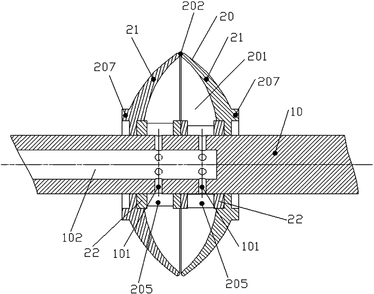
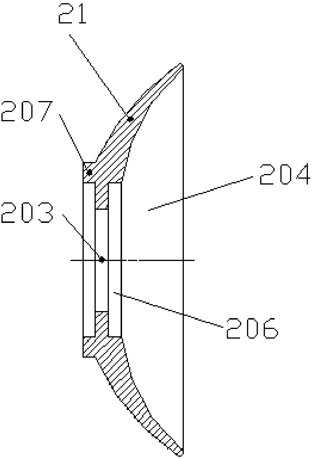
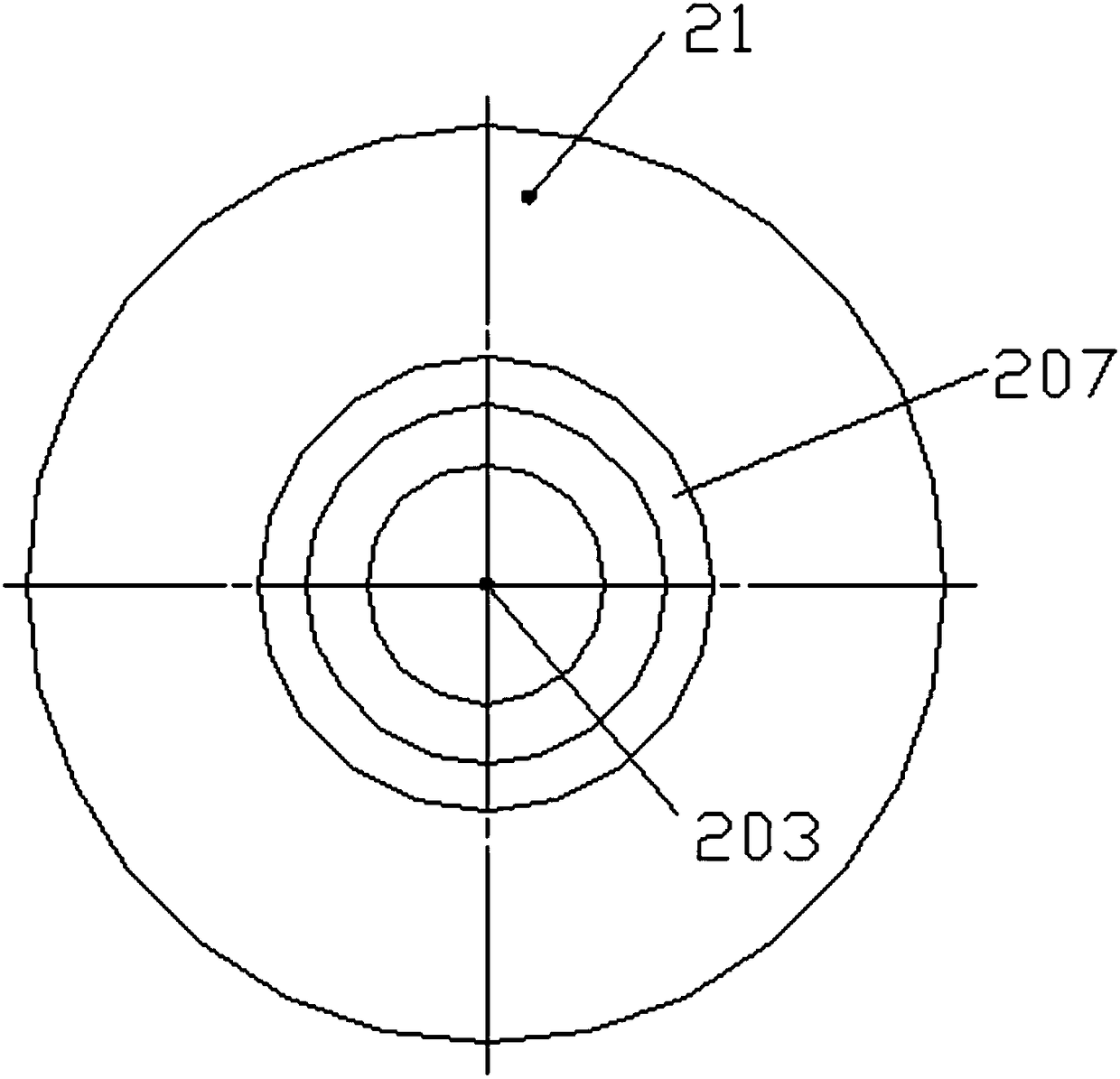

Embodiment Construction

[0026] The embodiments of the present invention will be described in detail below with reference to the accompanying drawings, but the present invention can be implemented in many different ways defined and covered by the claims.

[0027] refer to figure 1 , the preferred embodiment of the present invention provides a centrifugal oil atomization structure, which is used to arrange in the flame tube (not shown) of the engine to provide atomized fuel to the combustion chamber (not shown) of the engine. The oil atomization structure includes: a rotating main shaft 10 communicated with the fuel tank of the engine (not shown in the figure), and the rotating main shaft 10 is equipped with an oil throwing device for throwing the incoming fuel out in the state of an oil film under the action of centrifugal force to atomize the fuel. Atomizer 20. The oil throwing atomizer 20 has an oil throwing chamber 201 , and the rotating spindle 10 is provided with a plurality of oil outlet holes ...


PUM


Abstract

The invention discloses a centrifugal throwing oil atomization structure. The centrifugal throwing oil atomization structure comprises a rotating main shaft communicated with an oil tank of an engine; and the rotating main shaft is provided with a throwing oil atomizer for outwards throwing introduced fuel in an oil film state under the effect of centrifugal force to atomize the fuel. A throwing oil cavity is formed in the throwing oil atomizer; and the rotating main shaft is provided with multiple oil outlet holes for introducing the fuel in the throwing oil cavity. An annular oil outlet gap is formed in the throwing oil atomizer, and is communicated with the throwing oil cavity; and when the throwing oil atomizer rotates along with the rotating main shaft, the fuel fed in the throwing oil cavity from the oil outlet holes is outwards thrown in the oil film state from the oil outlet gap under the effect of centrifugal force after forming an oil film on the inner wall of the throwing oil cavity. The centrifugal throwing oil atomization structure is more uniform in peripheral fuel distribution, and is better in fuel atomization effect and dispersed distribution; and when the rotating speed of the main shaft is lower, the fuel atomization effect is excellent, the ignition is easy, and the combustion efficiency is high.

Description

technical field [0001] The invention relates to the field of gas turbine engines, in particular to a centrifugal oil-slinging atomization structure. Background technique [0002] A gas turbine engine is a device that converts the chemical energy of fuel into mechanical work. In the field of gas turbine engines, the engine generally organizes fuel and air to mix and burn through the combustion chamber, and the combustion products are discharged from the combustion chamber to drive the turbine to rotate and generate power output. Fuel is generally pressurized by the oil pump and then input into the fuel supply pipeline from the fuel tank, and then sprayed into the combustion chamber through the fuel supply pipeline through fuel atomization devices such as nozzles to complete combustion in the state of oil mist. The fuel atomization device is responsible for the atomization and dispersion distribution of the fuel, so as to facilitate the uniform distribution of the fuel in the...

Claims


Application Information

Patent Timeline
Patent Type & Authority Patents(China)
IPC IPC(8): F23R3/28
CPCF23R3/28
Inventor 严明超王倚阳胡好生陈延庚冯阳
Owner CHINA AVIATION POWER MACHINE INST
Learn More