Moving ground flatness detecting device, detecting system and detecting method

A detection device and detection method technology, applied in the direction of measuring devices, optical devices, instruments, etc., can solve problems such as height dislocation, surface layer and overall structure deformation, and safety hazards.

Inactive Publication Date: 2016-12-07
黑龙江省木材科学研究所
View PDF6 Cites 14 Cited by
  • Summary
  • Abstract
  • Description
  • Claims
  • Application Information

AI Technical Summary

Problems solved by technology

Each structural layer is affected by factors such as the flatness of the foundation ground, the frequency of use, the indoor and outdoor ambient air temperature, humidity, and light. The surface layer and the overall structure of the professional sports ground are easily deformed, resulting in local unevenness or High and low misalignment
Not only will it affect the performance of its sports field, but it will also cause major safety hazards for people who exercise on it
[0004] However, the existing professional sports ground surface testing instruments mostly focus on the detection of the wear resistance, friction performance, elasticity and hardness of the surface layer.
The detection equipment, detection methods and quality judgment of the surface smoothness of the sports ground are limited to the standard value limitation of macroscopic and simple detection tools and methods, and the ground flatness in the designated area and the relative height difference between multiple points cannot be measured, resulting in The flatness of sports venues varies greatly, which cannot meet the requirements of high-standard sports events and activities, which limits the development of the sports industry and the popularization of construction standardization of professional sports grounds

Method used


Image

  • Moving ground flatness detecting device, detecting system and detecting method
  • Moving ground flatness detecting device, detecting system and detecting method
  • Moving ground flatness detecting device, detecting system and detecting method

Examples


Embodiment Construction

[0047] The following will clearly and completely describe the technical solutions in the embodiments of the present invention with reference to the accompanying drawings in the embodiments of the present invention. Obviously, the described embodiments are only some, not all, embodiments of the present invention. Based on the embodiments of the present invention, all other embodiments obtained by persons of ordinary skill in the art without making creative efforts belong to the protection scope of the present invention.

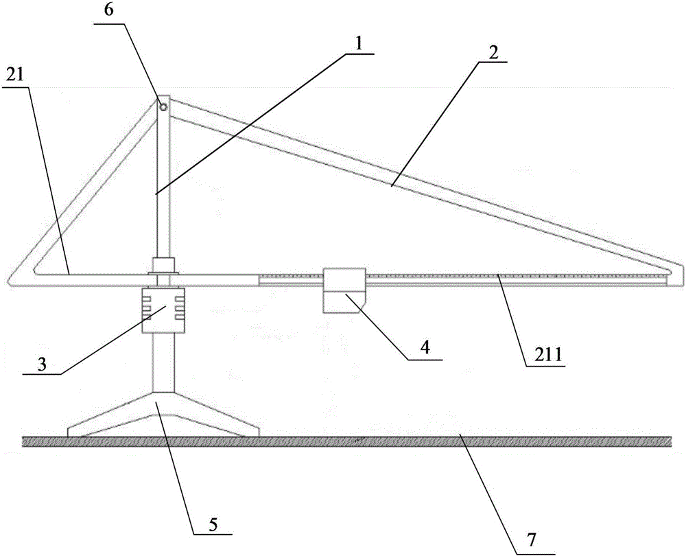
[0048] The object of the present invention is to provide a moving ground flatness detection device, which can drive the laser rangefinder to rotate through the rotary driver, so as to realize the measurement of the surface height of different positions of the ground to be measured under different measurement radii, and then determine the relative distance between multiple points. The height difference can effectively determine the flatness of the ground to be m...


PUM


Abstract

The invention discloses a moving ground flatness detecting device, a detecting system and a detecting method. The moving ground flatness detecting device comprises a main shaft which is vertically arranged on the ground to be detected, a tripod, a rotary drive and a laser range finder. A cross bar of the tripod is vertically fixed on the main shaft and can horizontally rotate around the main shaft. One end of the cross bar is a scale sliding rail. The rotary drive is fixed on the main shaft and is connected the cross bar to drive the cross bar to horizontally rotate. The laser range finder is arranged on the scale sliding rail of the cross bar, and can horizontally slide along the scale sliding rail to measure the height of the surface at different positions of the ground to be detected. According to the moving ground flatness detecting device provided by the invention, the rotary drive drives the scale sliding rail and the laser range finder to rotate; the height of the surface at different positions of the ground to be detected is measured at different measurement radius; the relative height difference among all points in the measured plane range can be determined; and the flatness of the ground to be detected is effectively determined.

Description

technical field [0001] The invention relates to the technical field of ground measurement, in particular to a testing device, a testing system and a testing method for the smoothness of a moving ground. Background technique [0002] Sports venues are mainly suitable for comprehensive activities such as entertainment performances, fitness, training, and competitive competitions held in sports venues. High-level professional competitive games such as CBA, NBA, etc. are usually carried out on special sports floors, and must be tested by professional organizations for their flatness and other related indicators. The relevant technical indicators of sports wooden floors are in line with national standards It can be put into operation only after meeting the specified requirements. [0003] The flatness index of the sports ground will directly affect the performance of athletes' technical level, sports injuries and fatigue, and even personal safety. At present, the ground of most...

Claims


Application Information

Patent Timeline
IPC IPC(8): G01B11/30
CPCG01B11/30
Inventor 王宏棣刘一楠何晓东王子奇周志芳
Owner 黑龙江省木材科学研究所
Why Eureka
Try Eureka