Large-scale dynamic load member fatigue performance testing method

A technology of fatigue performance and testing method, which is applied in the testing of machine/structural components, testing of mechanical components, measuring devices, etc. It can solve the problems that large-scale dynamic load components cannot be tested, and achieve the effect of low cost and convenient operation

Inactive Publication Date: 2016-12-07
INST OF METAL RESEARCH - CHINESE ACAD OF SCI
View PDF6 Cites 13 Cited by
  • Summary
  • Abstract
  • Description
  • Claims
  • Application Information

AI Technical Summary

Problems solved by technology

[0003] In order to solve the problem that large dynamic load components cannot be tested on conventional testing machines in the prior art, the purpose of the present invention is to provide a method for testing the fatigue performance of large dynamic load components, which can be tested on conventional fatigue testing machines through ingenious design Realization, low cost, easy operation, suitable for fatigue performance testing of rotor poles and yokes of pumped storage generator motors or other large dynamic load bearing components

Method used


Image

  • Large-scale dynamic load member fatigue performance testing method
  • Large-scale dynamic load member fatigue performance testing method
  • Large-scale dynamic load member fatigue performance testing method

Examples


Embodiment 1

[0027] By adopting the method of the invention and using a conventional testing machine, the fatigue performance test is carried out on the rotor magnetic pole and the magnetic yoke of the pumped storage generator motor.

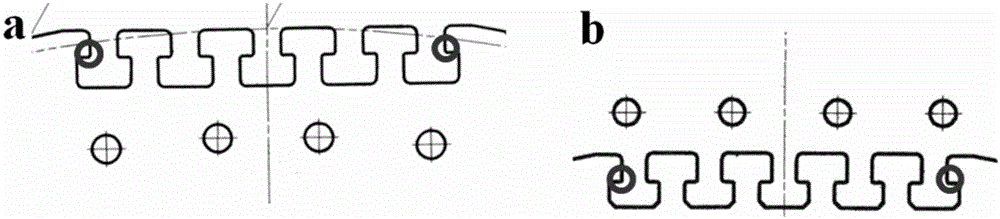
[0028] Magnetic poles and yokes are important parts of the rotor components ( figure 1 As shown), the magnetic pole is the basic element that constitutes the field winding, and is the magnetic induction component for the generator to establish a rotating magnetic field. The yoke is a yoke iron made of silicon steel sheets. On the one hand, it constrains the magnetic field lines generated by the induction coil to scatter outwards, and on the other hand, it acts as a magnetic shield. The magnetic pole and the yoke have a conjugated dovetail or T-tail structure, and the magnetic pole is fixed on the yoke through the magnetic pole key. The specific test process of the two components is as follows:

[0029] (1) Determine the most dangerous point of the rotor pol...

Embodiment 2

[0040] Difference with embodiment 1 is: the specific process of step (5) is different, and the present embodiment process is as follows:

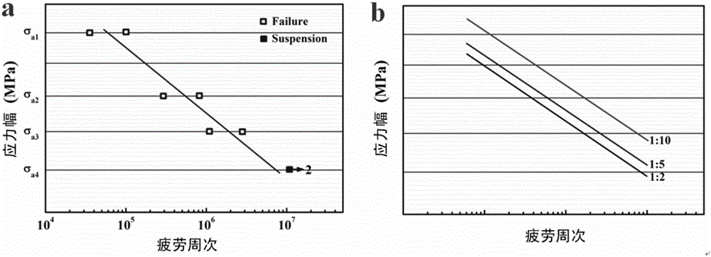
[0041] Calculate the load spectrum of service components under different working conditions (such as the start and stop of magnetic poles and yokes, load shedding and runaway) through finite element software, and then select the working conditions with more serious damage as the loading stress amplitude of miniature components (such as 150MPa~0.01MPa), and at least two miniature components with different ratios are selected for fatigue tests, and the quantitative relationship between the scaling ratio (1:2, 1:5 and 1:10) and the fatigue life of miniature components with different ratios is established (such as Figure 5 shown), and calculate the fatigue life of the service components by reasonable extrapolation (such as Figure 5 Points in , assuming that the logarithmic coordinates in the figure are linear).


PUM


Abstract

The invention discloses a large-scale dynamic load member fatigue performance testing method. The method comprises the steps: determining a most dangerous part of a magnet yoke of a magnetic pole, making the most dangerous part into a miniature member, reflecting the features of a key load, at different scales and a corresponding clamping tool; testing the stress fatigue performance of the miniature member on a fatigue machine, and searching the relation between the fatigue intensity, fatigue intensity index and fatigue intensity coefficient and the scales; and calculating the fatigue performance of a full-scale member. The invention solves a difficulty that a large-scale member cannot be tested on a conventional testing machine, and provides the large-scale dynamic load member fatigue performance testing method. The method can achieve the testing on the conventional testing machine through ingenious design, is lower in cost, is convenient to operate, and is suitable for other large-scale bearing dynamic load members.

Description

technical field [0001] The invention relates to the technical field of fatigue performance testing of service components, in particular to a method for testing the fatigue performance of large dynamic load components. Background technique [0002] With the rapid development of the national economy brought about by reform and opening up, large dynamic load components (rotors, shafts and rolls, etc.) are widely used. With the increase of service life, accidents or failures of components occur frequently, and the problem of operational safety becomes increasingly prominent. For example, pumped storage generator motors have high speed, bi-directional rotation, complex working conditions, frequent start-up, alternating stress and frequent fatigue during operation. In particular, the life prediction methods of pumped storage units currently in service in my country mostly rely on foreign technical support, and the operating units lack corresponding evaluation methods. The cost of...

Claims


Application Information

Patent Timeline
Patent Type & Authority Applications(China)
IPC IPC(8): G01M13/00
CPCG01M13/00
Inventor 庞建超姚戈张孟枭张哲峰
Owner INST OF METAL RESEARCH - CHINESE ACAD OF SCI
Why Eureka
Try Eureka