Interface friction property monitoring-based rolling-sliding friction life cycle test device

A technology of interface friction and testing equipment, which is applied in the direction of testing wear resistance and mechanical bearing testing, etc., can solve the problems that the actual state simulation of rolling bearings is not particularly suitable, the friction and wear process of rolling bearings cannot be effectively simulated, and the device system is complex, etc. load phenomenon, realize online health status monitoring, and have the effect of simple structure

Active Publication Date: 2016-12-07
XI AN JIAOTONG UNIV
View PDF7 Cites 19 Cited by
  • Summary
  • Abstract
  • Description
  • Claims
  • Application Information

AI Technical Summary

Problems solved by technology

In 2006, Ge Shirong and others invented a patent for a rolling friction and wear testing machine. This testing machine can simulate the friction and wear test under the rolling condition of ring-like friction pairs, but the device system is relatively complicated, and it can only be used for ring-like friction pairs. Effectively simulate the actual friction and wear process of rolling bearings
In 2011, Chen Wei and others invented the patent of high-speed rolling bearing slip device. Li Junning used this experimental device in his doctoral dissertation to study the influence of different slip factors, rotational speed and radial load on the oil film thickness. However, because the loading system operates at high speed The center of the electric spindle is the fulcrum, and it is easy to cause unbalanced load when loading. The higher the load, the more obvious the unbalanced load
In 2014, Wei Jing and others invented a patent for a variable load rolling friction and wear tester. This device changed the loading method and added the lubricating oil temperature control method based on the device invented by Chen Wei, but its friction pair is also limited to Annular friction pairs are not particularly suitable for the actual state simulation of rolling bearings

Method used


Image

  • Interface friction property monitoring-based rolling-sliding friction life cycle test device
  • Interface friction property monitoring-based rolling-sliding friction life cycle test device

Examples


Embodiment Construction

[0027] The present invention is described in detail below in conjunction with accompanying drawing.

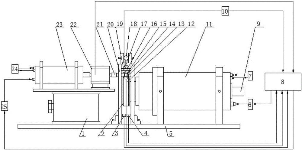
[0028] refer to figure 1, a rolling friction life testing device based on interface friction performance monitoring, comprising a bracket 5, one end of the bracket 5 is fixed with a lifting platform 1, a high-speed electric spindle 23 is arranged on the lifting platform 1, the front end of the high-speed electric spindle 23 and the torque One end of the sensor 22 is connected; the high-speed electric spindle 23 and the torque sensor 22 are fixed on the platform of the lifting platform 1 and can move up and down with the adjustment of the lifting platform; the other end of the torque sensor 22 is connected to the measured object through the elastic coupling 21 Replaceable rolling body 14; during the installation process, it is necessary to ensure the coaxiality of the axis of the high-speed electric spindle 23, the axis of the torque sensor 22 and the axis of the rolling body 1...


PUM


Abstract

The invention relates to an interface friction property monitoring-based rolling-sliding friction life cycle test device. A high-speed electric spindle on a support lifting platform is connected with a torque sensor; one end of the torque sensor is connected with an exchangeable rolling body in a measured object; two ends of the rolling body are provided with rolling bearings; the rolling bearings area arranged in a vertical guide rail; a pressing plate is arranged above the rolling bearings; a groove for accommodating a ball is arranged on the upper surface of the pressing plate; the upper part of the ball contacts with the fulcrum plane of a pressing rod; a lever is arranged on an upright column; the tail end of the lever is connected with the nut of a sensor on a support through a steel wire rope; one end of the support is provided with a low-speed motorized spindle; and the front end of the low-speed motorized spindle is equipped with the bearing inner ring of the measured object. With the test device of the invention adopted, the actual working condition of each roller and a bearing inner ring in the operation process of a cylindrical roller bearing can be simulated; the cause of abrasion caused by the change of interface contact is obtained; and a reliable data guarantee and technical support can be provided for the life cycle health condition monitoring and condition-based repair of the key friction pair of a rolling bearing.

Description

technical field [0001] The invention belongs to a rolling-sliding basic performance test device, in particular to a rolling-sliding friction life-span testing device based on interface friction performance monitoring. Background technique [0002] Rolling bearings are an essential part of the load-bearing transmission system of aero-engines, and their performance and quality directly affect the service life and reliability of aero-engines. With the development of rolling bearings in theoretical research, structural design, manufacturing technology, etc., the performance and reliability of bearings have been greatly improved, but at the same time, aviation technology is developing rapidly, and the thrust-to-weight ratio and power of engines are also increasing. The working conditions of the main shaft bearings are developing towards complex and harsh working conditions such as high temperature, high speed and heavy load, which also put forward higher requirements for the perf...

Claims


Application Information

Patent Timeline
Patent Type & Authority Applications(China)
IPC IPC(8): G01M13/04G01N3/56
CPCG01M13/04G01N3/56
Inventor 武通海段志和陈谓郭帅伟
Owner XI AN JIAOTONG UNIV
Why Eureka
Try Eureka