
Array substrate, display panel and display device

A technology of array substrates and pads, applied in nonlinear optics, instruments, optics, etc., can solve problems such as circuit signals cannot be loaded normally, affect liquid crystal rotation, and defects

Inactive Publication Date: 2016-12-07
BOE TECH GRP CO LTD +1
View PDF6 Cites 4 Cited by
  • Summary
  • Abstract
  • Description
  • Claims
  • Application Information

AI Technical Summary

Problems solved by technology

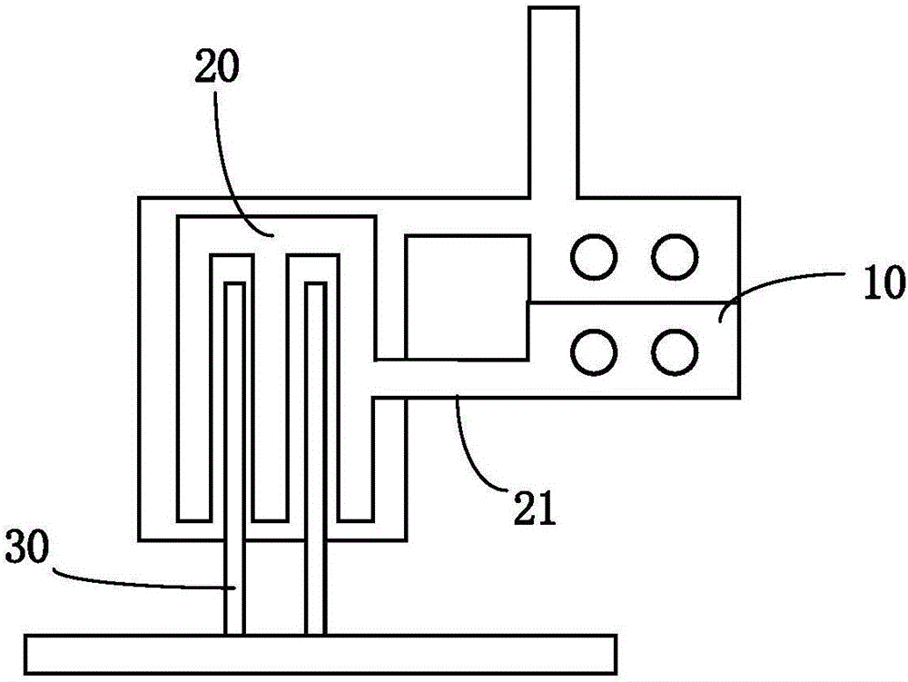
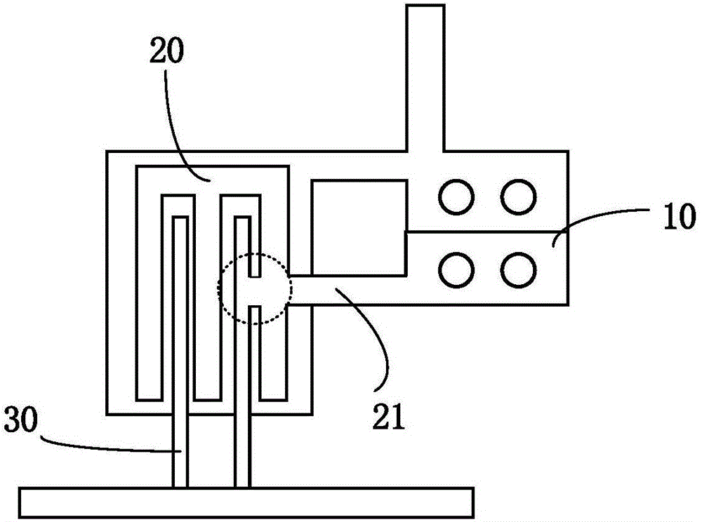
[0005] In the current GOA products, the drain connection lead 21 is in the middle of the source-drain channel (SD Channel). This design makes the pattern lines in the middle of the SD Channel denser, and is affected by the optical proximity effect during exposure. ,like figure 2 As shown, the electrode line of the drain 20 at the position where the drain connection lead 21 is located will be distorted, and the probability of failure (circuit short circuit) between the drain electrode 30 and the source electrode 30 is relatively high, and the product yield (control Margin) is low.
[0006] The current short circuit in the signal transmission area of ​​GOA products is mainly detected through the final array test process (Final ArrayTest), which cannot be repaired. Once it occurs, it will have a great impact on the product yield. It cannot be loaded normally, which will affect the electrical characteristics of TFT, and then affect the rotation of liquid crystal

Method used


Image

  • Array substrate, display panel and display device
  • Array substrate, display panel and display device
  • Array substrate, display panel and display device

Examples


Embodiment Construction

[0025] In order to make the objectives, technical solutions, and advantages of the embodiments of the present invention clearer, the technical solutions of the embodiments of the present invention will be described clearly and completely in conjunction with the accompanying drawings of the embodiments of the present invention. Obviously, the described embodiments are part of the embodiments of the present invention, rather than all of the embodiments. Based on the described embodiments of the present invention, all other embodiments obtained by a person of ordinary skill in the art fall within the protection scope of the present invention.

[0026] In the prior art, the drain connection line of the thin film transistor in the driving circuit area of ​​the GOA product used to connect with the driving circuit pad is drawn from the middle part of the source and drain channel, which will be affected by the optical effect during the exposure process. However, there is a technical prob...


PUM


Abstract

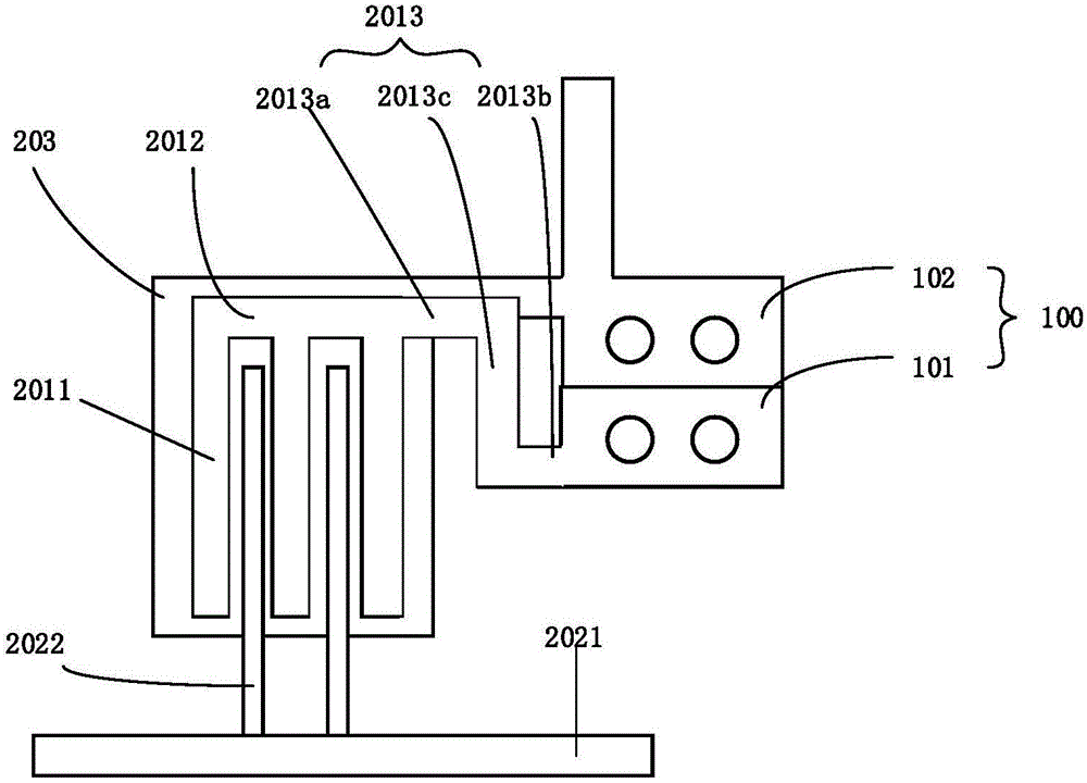
The invention provides an array substrate, a display panel and a display device. The array substrate comprises a display region and a driving circuit region, the driving circuit region comprises multiple driving circuit pads and multiple thin-film transistors, each thin-film transistor comprises a source electrode and a drain electrode, each drain electrode comprises multiple first comb tooth electrodes which are spaced and parallelly arranged and a first comb handle electrode connecting the first comb tooth electrodes, and each source electrode comprises second comb tooth electrodes which are spaced and parallelly arranged and a second comb handle electrode connecting the second comb tooth electrodes; each drain electrode and the corresponding source electrode are in interpolation structure distribution, each drain electrode further comprises a drain electrode connecting lead, and the first end of each drain electrode connecting lead is connected with the corresponding first comb handle electrode while the second end of the same is connected with the corresponding driving circuit pad. Circuits with the drain electrodes subject to influence of optical proximity effect in the driving circuit region of a GOA (gate on array) product are arranged in an optimized manner, so that influence of the optical proximity effect in the process of exposure is avoided, and circuit short-out of the driving circuit region is improved.

Description

Technical field [0001] The present invention relates to the field of display technology, in particular to an array substrate, a display panel and a display device. Background technique [0002] With the development of TFT-LCD (thin film transistor-liquid crystal display) manufacturing technology, various new technologies are rapidly applied and developed. GOA (Gate driver On Array or (Gate On Array) technology is a design in TFT-LCD, which integrates the gate drive circuit of the LCD panel on the substrate, thereby improving the integration of the LCD panel and reducing the gate The usage rate of extremely drive IC has been widely used. [0003] With the development of TFT technology, the line spacing of photoetching lines is getting narrower and narrower, and the influence of optical proximity effect is getting bigger and bigger. Optical proximity effect refers to the line proximity distortion caused by diffraction in the optical imaging process after exposure with the same desi...

Claims


Application Information

Patent Timeline
IPC IPC(8): G02F1/1345G02F1/1362
CPCG02F1/13454G02F1/136286
Inventor 肖文龙张心杰吴四权章开兵
Owner BOE TECH GRP CO LTD
Learn More