Tripping device of low-voltage circuit breaker

A technology for low-voltage circuit breakers and tripping devices, which is applied to emergency protection devices, circuits, and parts of protective switches. It can solve the problems of adjusting the dial code to occupy an obvious height dimension and increasing the volume of the circuit breaker, so as to eliminate the reduction in size , Save parts and simplify manufacturing

Inactive Publication Date: 2016-12-07
CHANGSHU SWITCHGEAR MFG CO LTD (FORMER CHANGSHU SWITCHGEAR PLANT)
View PDF9 Cites 2 Cited by
  • Summary
  • Abstract
  • Description
  • Claims
  • Application Information

AI Technical Summary

Problems solved by technology

However, as the aforementioned adjustable overload tripping device composed of bimetallic elements, because it is adjusted by adjusting the dial located (corresponding) above the drawbar (that is, the overload adjustable dial) Adjustment to change the distance between the drawbar and the bimetal element (also known as "gap") to achieve the adjustment of the rated current, so the adjustment dial often occupies an obvious height dimension, which increases the volume of the circuit breaker more obvious

Method used


Image

  • Tripping device of low-voltage circuit breaker
  • Tripping device of low-voltage circuit breaker
  • Tripping device of low-voltage circuit breaker

Examples


Embodiment 1

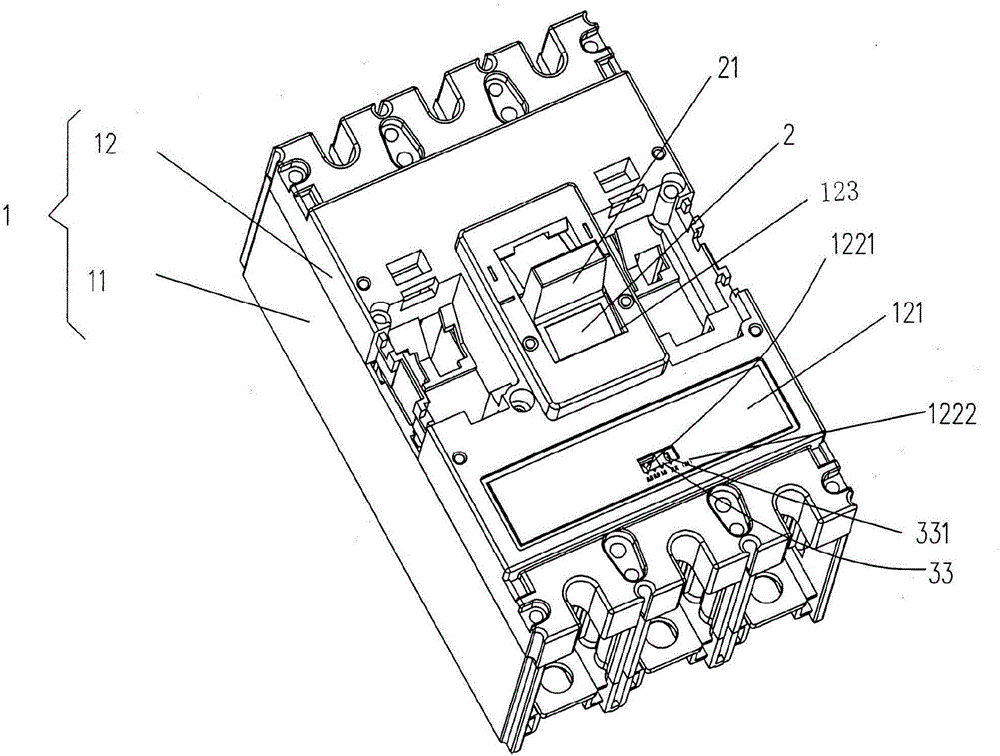
[0027] See figure 1 , Figure 4 to Figure 7 , shows a housing 1 and an operating mechanism 2 of the structural system of a low-voltage circuit breaker (this embodiment is a low-voltage molded case circuit breaker, the same below). The housing 1 includes a base 11 and a Cooperating with the base cover 12 , the operating mechanism 2 is arranged in the base 11 and extends out of the base cover 12 . A cover plate is disposed on the base cover 12 and at one end of the base cover 12 , the cover plate includes a first small cover 121 and a second small cover 122 , and the second small cover 122 covers the first small cover 121 . A drawbar adjustment window 1211 is opened on the first small cover 121 , and a display window 1221 corresponding to the drawbar adjustment window 1211 is opened on the second small cover 122 . Depend on figure 1 As shown, an operating mechanism handle cavity 123 is formed on the base cover 12 and generally located in the middle of the base cover 12. The a...

Embodiment 2

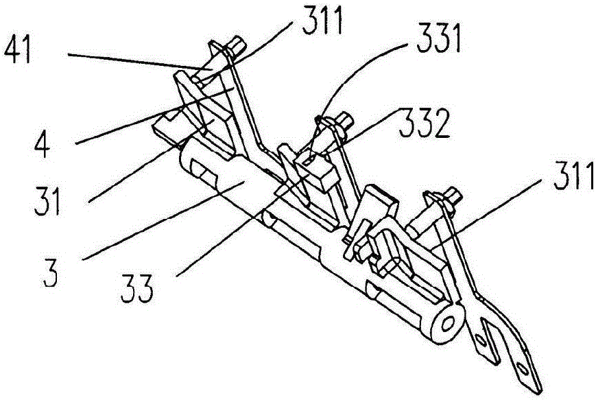
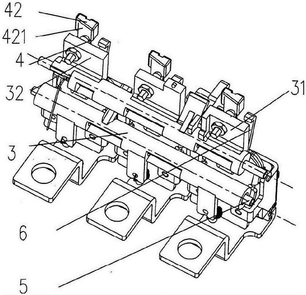
[0036] See image 3 , an actuating block 42 is arranged (embedded in this embodiment) on the upper part of the aforementioned bimetallic element 4, and an actuating block actuator 32 is fixed on the aforementioned traction rod 3 at a position corresponding to the actuating block 42 An actuating block actuating slope 421 is formed on the side of the aforesaid actuating block 42 facing the actuating block actuator 32. When the aforesaid towing rod adjustment window 1211 is used to adjust the towing rod 3 along the desired pivoting axis of the towing rod 5. When the axial displacement is adjusted, the gap between the aforementioned actuating block actuating slope 421 and the aforementioned actuating block actuating member 32 changes so as to realize the adjustment of the aforementioned current gear.

[0037] In this embodiment, the aforesaid actuating block actuator 32 is a pin shaft or a screw, specifically as the description of the drawbar actuating member 41, the aforesaid act...


PUM


Abstract

The invention provides a tripping device of a low-voltage circuit breaker. The tripping device comprises a shell, wherein the shell comprises a base and a base cover; a traction rod adjusting window is formed in the base cover; the tripping device comprises a traction rod arranged in the base and at least one bimetallic element for actuating the traction rod to act; the traction rod is provided with a traction rod adjusting flange; the traction rod adjusting flange corresponds to the traction rod adjusting window; and when axial adjustment is carried out on the traction rod through the traction rod adjusting window, the distance between the traction rod and the bimetallic element is changed to achieve adjustment on current gears. The distance between the traction rod and the bimetallic element is changed directly through axial adjustment on the traction rod along a traction rod pivot shaft through the traction rod adjusting window to achieve adjustment on different current gears, so that the factor of affecting size reduction of the circuit breaker in the height direction can be eliminated; the requirements of miniaturization development of the circuit breaker can also be met; the space, occupied by an overload allocation code, in the height and parts are saved; and manufacturing, simplifying of the process and reduction of the cost are facilitated.

Description

technical field [0001] The invention belongs to the technical field of low-voltage electrical appliances, and in particular relates to a tripping device for a low-voltage circuit breaker. Background technique [0002] The tripping device mentioned above mainly refers to the magnetic tripping device, more precisely, it refers to the thermal magnetic tripping device (the industry is also used to call it "thermal magnetic tripping device"), the structure of the thermal magnetic tripping device There are two main forms: one is an overload delay protection tripping device composed of bimetallic elements; the other is a short-circuit protection instantaneous tripping device in the form of an electromagnet. When an abnormal current in the circuit is detected, the action of the thermomagnetic tripping device activates the tripping of the circuit breaker and cuts off the faulty circuit. In addition, according to whether the current setting value of the circuit breaker is adjustable ...

Claims


Application Information

Patent Timeline
Patent Type & Authority Applications(China)
IPC IPC(8): H01H71/74H01H71/16
CPCH01H71/7436H01H71/16
Inventor 王炯华顾建青唐维春
Owner CHANGSHU SWITCHGEAR MFG CO LTD (FORMER CHANGSHU SWITCHGEAR PLANT)
Why Eureka
Try Eureka