
Image sensing device

An image sensing and sensing surface technology, applied in radiation control devices, image communication, television, etc., can solve problems such as image distortion, easy light divergence, and difficulty in reducing the total thickness of image sensing devices

Inactive Publication Date: 2016-12-07
XINTEC INC
View PDF8 Cites 3 Cited by
  • Summary
  • Abstract
  • Description
  • Claims
  • Application Information

AI Technical Summary

Problems solved by technology

In this way, when the image sensing surface of the semiconductor device senses the image, the light is easy to diverge, which easily leads to image distortion
[0004] In addition, when the image sensing device needs to be miniaturized, it is difficult to reduce the total thickness of the image sensing device by using a chip package bonded to a circuit board with solder balls.

Method used


Image

  • Image sensing device
  • Image sensing device
  • Image sensing device

Examples


Embodiment Construction

[0053] A number of embodiments of the present invention will be disclosed in the following figures. For the sake of clarity, many practical details will be described together in the following description. It should be understood, however, that these practical details should not be used to limit the invention. That is, in some embodiments of the present invention, these practical details are unnecessary. In addition, for the sake of simplifying the drawings, some known and commonly used structures and elements will be shown in a simple and schematic manner in the drawings.

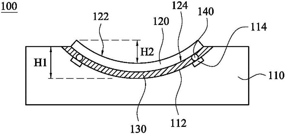
[0054] figure 1 A cross-sectional view of an image sensing device 100 according to an embodiment of the present invention is shown. As shown in the figure, the image sensing device 100 includes a circuit board 110 , a chip package 120 and an adhesive layer 130 . Wherein, the circuit board 110 has a concave portion 112 . The chip package 120 has a sensing surface 122 and a bonding surface 124 opposite to...


PUM


Abstract

An image sensing device includes a printed circuit board, a chip package, and an adhesive layer. The printed circuit board has a concave portion. The chip package has a sensing surface and a bonding surface that is opposite to the sensing surface. The adhesive layer is disposed between the bonding surface of the chip package and the concave portion of the printed circuit board. The adhesive layer has an aggregation force. The chip package is bent through a surface of the concave portion and the aggregation force, such that the sensing surface of the chip package is an arc surface. The image sensing device of the present invention not only reduces the possibility of image distortion, but also reduces the overall thickness of the image sensing device, which contributes to the miniaturization design.

Description

technical field [0001] The invention relates to an image sensing device. Background technique [0002] When making an image sensing device, the chip package can be placed on the circuit board using soldering technology or Surface Mount Technology (SMT), so that the solder balls on the back of the chip package can be electrically connected to the contacts of the circuit board. connect. [0003] Since the size of the solder balls is approximately the same, and the chip package is not specially designed, the known chip packages are all parallel to the circuit board, so that the front side of the chip package (ie, the image sensing surface) is a horizontal plane. In this way, when the image sensing surface of the semiconductor element senses an image, light tends to diverge, which easily causes image distortion. [0004] In addition, when the image sensing device needs to be miniaturized, it is difficult to reduce the total thickness of the image sensing device by using a chip...

Claims


Application Information

Patent Timeline
Patent Type & Authority Applications(China)
IPC IPC(8): H01L27/146
CPCH01L27/14601H01L27/14618H01L27/14687H04N23/54
Inventor 刘沧宇廖季昌
Owner XINTEC INC
Learn More