A Novel LTCC Broadband Circularly Polarized Microstrip Patch Array Antenna

A microstrip patch and array antenna technology, which is applied to antennas, resonant antennas, antenna arrays, etc., can solve the problems of high requirements on the dimensional accuracy of the cut corner of the patch, increase the complexity of the antenna structure, and unfavorable miniaturization of the antenna. Improve the performance of circular polarization, simple structure, simple and convenient adjustment

Inactive Publication Date: 2019-04-05
UNIV OF ELECTRONICS SCI & TECH OF CHINA
View PDF3 Cites 0 Cited by
  • Summary
  • Abstract
  • Description
  • Claims
  • Application Information

AI Technical Summary

Problems solved by technology

[0003] However, the input impedance of the microstrip patch antenna is very sensitive to changes in frequency, resulting in a very narrow impedance bandwidth; the current common methods of widening the microstrip patch antenna include increasing the thickness of the substrate, using a multi-layer structure, and additional impedance matching. But these are not only not conducive to the miniaturization of the antenna, but also make the antenna structure more complicated
In addition, in realizing the circular polarization of the microstrip patch antenna, there are currently common methods of using multiple feeds and patch angle cutting, but the former increases the complexity of the antenna structure and reduces the gain of the antenna, and the latter has a negative impact on the antenna. Higher dimensional accuracy requirements for patch cut corners
The contradiction between circularly polarized microstrip patch array antenna and its low profile, circular polarization, high gain, and wide frequency band has not been well resolved.

Method used


Image

  • A Novel LTCC Broadband Circularly Polarized Microstrip Patch Array Antenna
  • A Novel LTCC Broadband Circularly Polarized Microstrip Patch Array Antenna
  • A Novel LTCC Broadband Circularly Polarized Microstrip Patch Array Antenna

Examples


Embodiment Construction

[0023] The present invention will be further described in detail below with reference to the drawings and embodiments, but the present invention is not limited thereto.

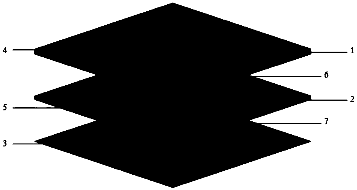
[0024] This embodiment provides a novel LTCC broadband circularly polarized microstrip patch array antenna, its structure is as follows Figure 1 to Figure 4 As shown, the center frequency of the antenna is 10GHz, and its performance test results are as follows Figure 5 , Figure 6 , Figure 7 As shown, the antenna can achieve an impedance bandwidth of 1.68GHz within a section thickness of 2.1mm, a maximum gain of 12.02dB, and an antenna axial ratio as low as 1.7dB.

[0025] The above-mentioned novel LTCC broadband circularly polarized microstrip patch array antenna includes the following structures:

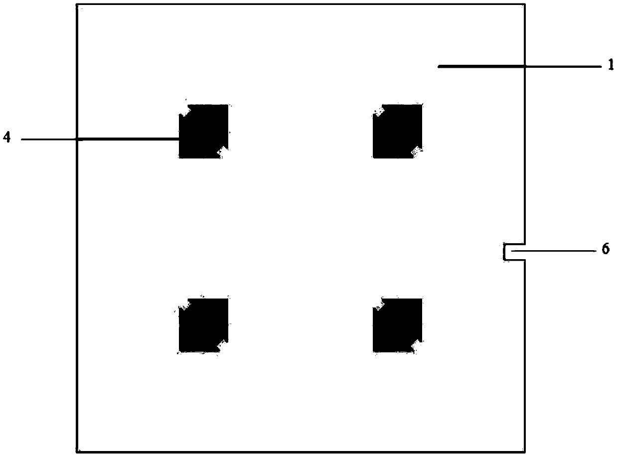
[0026] Upper dielectric substrate (1): The substrate is laminated with 12 LTCC cast films with a thickness of 0.1mm and a dielectric constant of 5.9. The lateral dimension of the substrate is 44mm and the l...


PUM


Abstract

The invention belongs to the technical field of antennas, and in particular relates to a novel LTCC wideband circularly polarized microstrip patch array antenna, which is used to overcome the disadvantages of the existing circularly polarized microstrip patch array antenna in consideration of its low profile, circular polarization, and high Insufficient in terms of gain and broadband. The antenna includes a grounded metal layer, a lower dielectric substrate, a lower metal patch antenna, an upper dielectric substrate, and an upper metal patch antenna stacked in sequence from bottom to top. The upper and lower metal patch antennas are respectively composed of several The upper and lower metal patch units are composed of square metal patches with cut corners of the same size and rectangular grooves are opened at the corners, and rectangular grooves are opened on the four sides of the upper metal patch unit. Slits, rectangular slits are also opened on the other three sides of the metal patch unit on the lower layer except the feeding side. The present invention can have smaller size, higher gain, better circular polarization performance and wider frequency bandwidth under the limitation of the same number of array elements.

Description

technical field [0001] The invention belongs to the technical field of antennas, and in particular relates to a novel LTCC wideband circularly polarized microstrip patch array antenna. Background technique [0002] Microstrip array antenna is a part of radar system that transmits and receives electromagnetic waves, and its performance directly affects the accuracy of radar detection results. Therefore, for radar systems, the design of array antenna is particularly important. Compared with the array radiation unit, the array antenna has higher gain, narrower beam, stronger directivity and spatial beam scanning characteristics. The circularly polarized antenna has the orthogonality of rotation; it can receive incoming waves with any polarization, and its radiated waves can also be received by any polarization antenna; the circularly polarized wave is incident on a symmetrical target, and the reflected wave is anti-rotated. Therefore, the circularly polarized microstrip patch ...

Claims


Application Information

Patent Timeline
Patent Type & Authority Patents(China)
IPC IPC(8): H01Q1/38H01Q1/50H01Q9/04H01Q21/00
CPCH01Q1/38H01Q1/50H01Q5/28H01Q9/0407H01Q21/00
Inventor 张怀武付小利杨青慧刘成
Owner UNIV OF ELECTRONICS SCI & TECH OF CHINA
Why Eureka
Try Eureka