RFID tag
a technology of rfid tags and tags, applied in the direction of instruments, resonant antennas, burglar alarm mechanical actuation, etc., can solve the problems of inability to add or update new information to the barcode itself, troublesome reading of barcodes, and poor gain, so as to increase the frequency bandwidth and increase the transmission frequency. , the effect of simplifying the construction of the power supply section
- Summary
- Abstract
- Description
- Claims
- Application Information
AI Technical Summary
Benefits of technology
Problems solved by technology
Method used
Image
Examples
embodiment 1
(A) Embodiment 1
(a) Construction
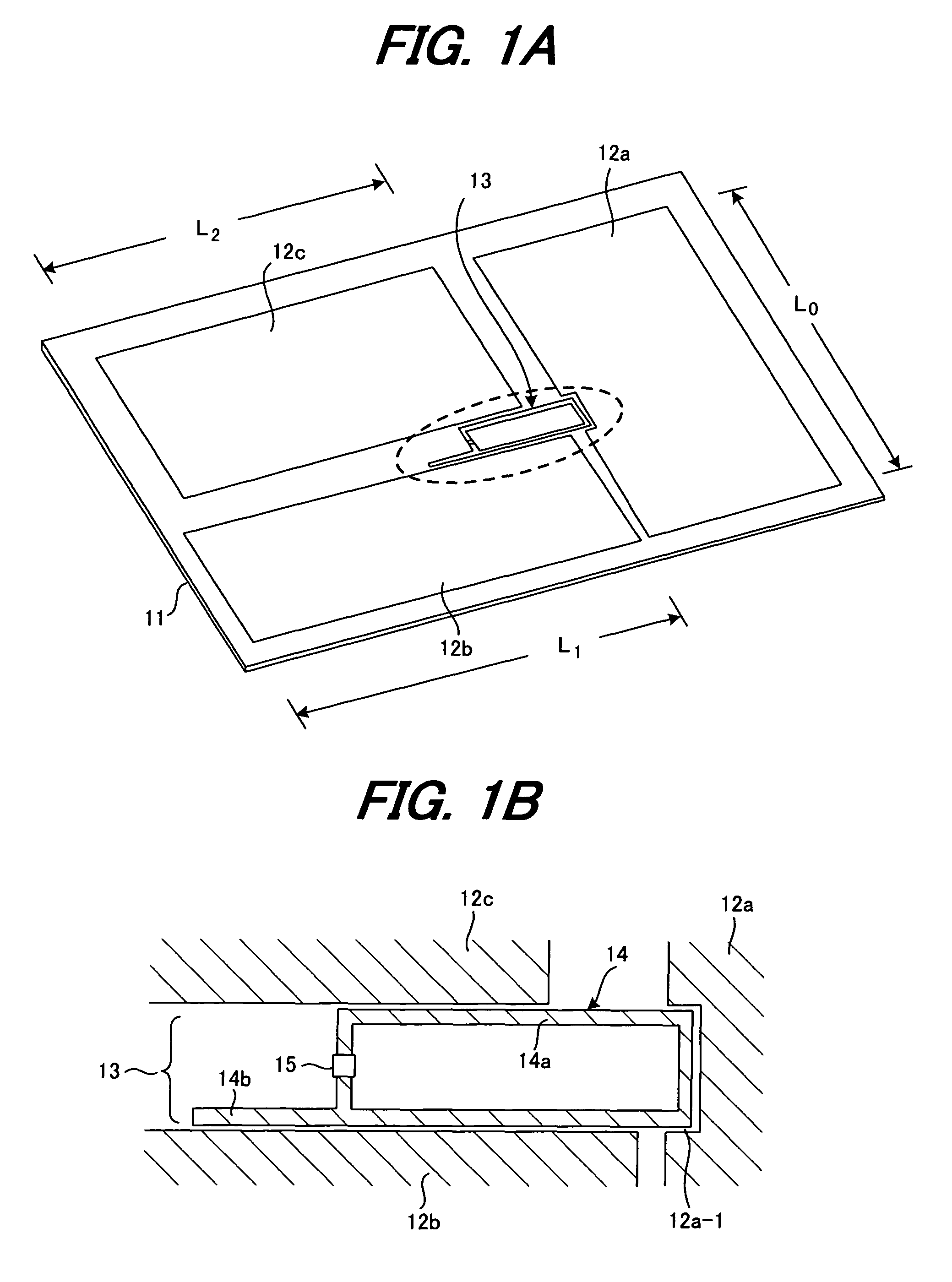
[0038]FIGS. 1A and 1B are drawings explaining a RFID tag of a first embodiment of the invention, where FIG. 1A is a pictorial drawing and FIG. 1B is an enlarged view of a part enclosed by a dotted line in FIG. 1A.
[0039]The RFID tag of this first embodiment is made by etching the rear surface of a double-sided printed circuit board 11 to form three patch antennas 12a to 12c, which function as a tag antenna, and a power-supply pattern section 14, and then mounting a tag LSI 15 on that power-supply pattern section 14 using a chip bonding technique. The power-supply pattern section 14 and the tag LSI 15 form a power-supply element 13. An electrically conductive pattern (not shown in the figure) on the rear surface of the printed circuit board 11 is used as a ground (all surfaces are metallic).
[0040]The sizes L0 to L2 of the patch antennas 12a to 12c are set so that the resonant frequencies will correspond with the transmission frequencies used by UHF band...
embodiment 2
(B) Embodiment 2
(a) Construction
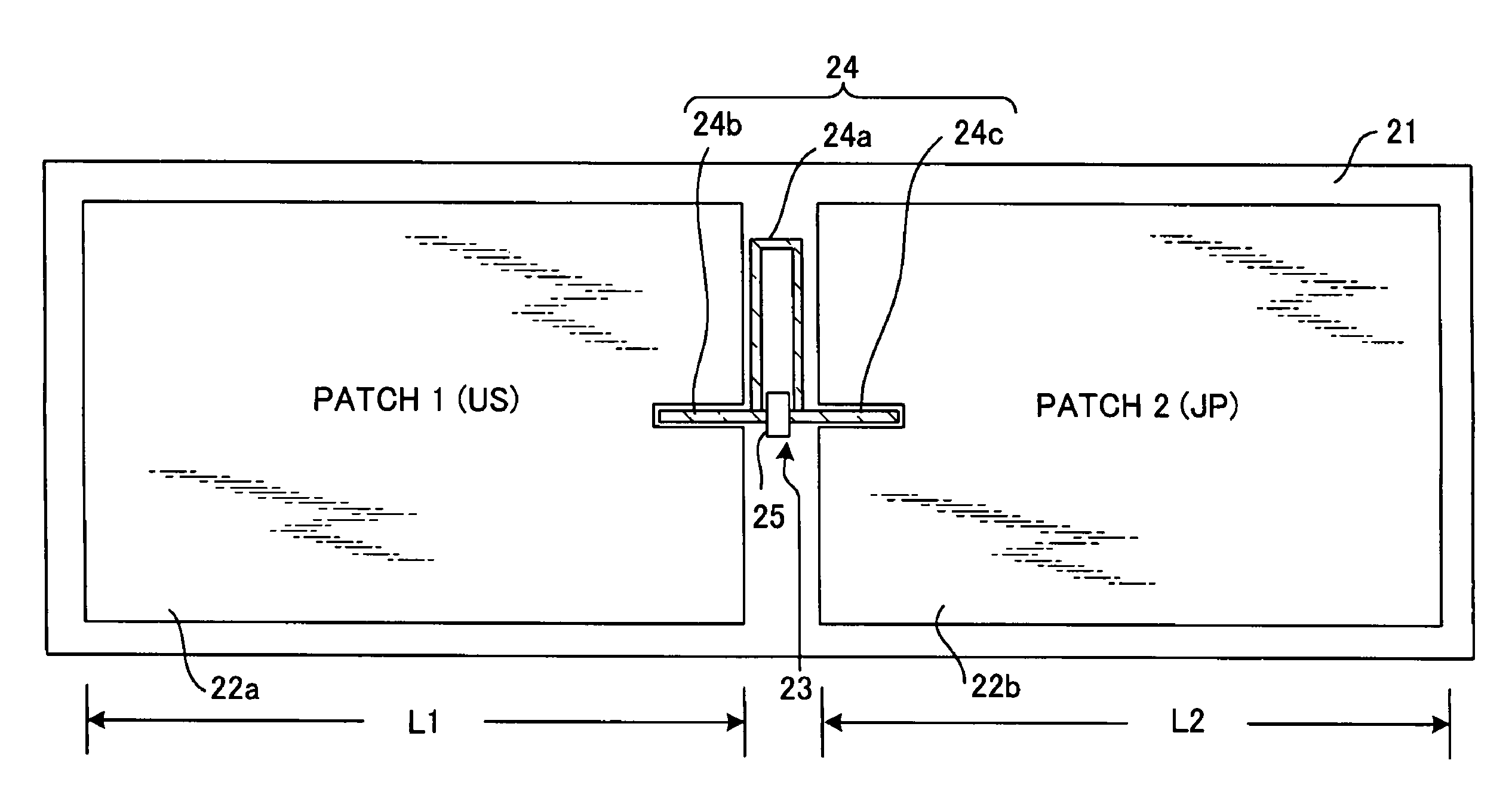
[0061]FIGS. 9A and 9B are drawings explaining the RFID tag of a second embodiment of the invention, where FIG. 9A is a top view, and FIG. 9B is an enlarged view of the main part.
[0062]The RFID tag of this second embodiment is made by etching the surface of a double-sided printed circuit board 21 to form two patch antennas 22a to 22b, which function as tag antennas, and a power-supply pattern section 24, and by mounting a tag LSI 25 onto the power-supply pattern section 24 by a chip bonding technique. The power-supply pattern section 24 and tag LSI 25 form a power-supply element 23. The electrically conductive pattern (not shown in the figure) on the rear surface of the printed circuit board is used as a ground (all surfaces are metallic).
[0063]The sizes L1 to L2 of the patch antennas 22a to 22b are set so that the resonant frequencies correspond with the transmission frequencies used by UHF RFID tags for the USA and Japan. The power-supply pattern sec...
embodiment 3
(C) Embodiment 3
(a) Construction
[0085]FIGS. 17A and 17B are drawings explaining a RFID tag of a third embodiment of the invention, where FIG. 17A is a top view, and FIG. 17B is an enlarged view of the main parts.
[0086]The RFID tag of this third embodiment is made by etching the surface of a double-sided printed circuit board to form two patch antennas 32a to 32b that function as tag antennas, and a power-supply pattern section 34, and by mounting a tag LSI 35 onto the power-supply pattern section 34 by a chip bonding technique. The power-supply pattern section 34 and tag LSI 35 form a power-supply element 33. The electrically conductive pattern (not shown in the figure) on the rear surface of the printed circuit board is used as a ground (all surfaces are metallic).
[0087]The sizes L1 to L2 of the patch antennas 32a to 32b are set so that the resonant frequencies correspond with the transmission frequencies used by UHF RFID tags for the USA and Japan. The power-supply pattern section...
PUM
 Abstract
Description
Claims
Application Information
 - R&D
- Intellectual Property
- Life Sciences
- Materials
- Tech Scout
- Unparalleled Data Quality
- Higher Quality Content
- 60% Fewer Hallucinations
Browse by: Latest US Patents, China's latest patents, Technical Efficacy Thesaurus, Application Domain, Technology Topic, Popular Technical Reports.
© 2025 PatSnap. All rights reserved.Legal|Privacy policy|Modern Slavery Act Transparency Statement|Sitemap|About US| Contact US: help@patsnap.com


