Antenna structure and radio communication apparatus including the same

a radio communication apparatus and antenna technology, applied in the direction of antennas, antenna details, elongated active element feeds, etc., can solve the problems of antenna characteristics deterioration, frequency bandwidth for radio communication is likely to decrease, and the like, so as to improve the antenna characteristics, reduce the loss of conductive and dielectric losses, and increase the frequency bandwidth for radio communication

Inactive Publication Date: 2008-12-30
MURATA MFG CO LTD
View PDF18 Cites 10 Cited by
  • Summary
  • Abstract
  • Description
  • Claims
  • Application Information

AI Technical Summary

Benefits of technology

[0011]In the present invention, the configuration given below serves as means for solving the problems. That is, an antenna structure according to the present invention includes a ground region in which a ground is formed, a non-ground region in which the ground is not formed, the ground region and the non-ground region are provided next to each other such that the non-ground region is disposed on one end of a board; a dielectric base member of a rectangular column shape provided in the non-ground region of the board or on the non-ground region and outside of the board; and a feed radiation electrode provided on the dielectric base member; an outer side surface of the dielectric base member along an edge of the one end of the board defines a side surface near a top side, and in the non-ground region of the board or outside the board, a feed electrode connected to a circuit for radio communication provided in the ground region is provided along a side surface of the dielectric base member or an outer edge of the board; one end of the feed radiation electrode defines a feed end, which is connected to the feed electrode, on the side surface of the dielectric base member near the top side, the other end of the feed radiation electrode defines an open end, and the feed radiation electrode has a configuration in which a current path extending from the feed end to the open end has a loop shape so as to be provided on at least the side surface near the top side and an upper surface next to the side surface of the dielectric base member; a feed radiation electrode portion formed on the side surface of the dielectric base member near the top side forms a capacitance for improving antenna characteristics between the feed radiation electrode portion and the feed electrode provided along the side surface of the dielectric base member or the outer edge of the board in the non-ground region of the board.
[0012]According to the present invention, the feed radiation electrode has a configuration in which the current path extending from the feed end to the open end has a loop shape so as to be provided on at least the side surface near the top side and the upper surface of the dielectric base member. That is, the feed radiation electrode has a configuration to use at least the side surface near the top side and the upper surface of the dielectric base member. Thus, compared with a case where the feed radiation electrode is provided only on the upper surface of the dielectric base member, an electromagnetic field of the feed radiation electrode is dispersed. Accordingly, since conductive loss and dielectric loss can be reduced, the antenna characteristics can be improved.
[0013]In addition, since the electromagnetic field of the feed radiation electrode is dispersed, a Q-value, which is an antenna characteristic, can be reduced. Thus, an increase in the frequency bandwidth for radio communication can be achieved.

Problems solved by technology

Thus, a problem occurs in which a Q-value, which is an antenna characteristic, is likely to increase and in which a frequency bandwidth for radio communication is likely to decrease.
In addition, there is a problem in which antenna characteristics deteriorate due to increases in conductive loss and dielectric loss.
This causes a problem in which conductive loss increases in the feed radiation electrode 7 and the non-feed radiation electrode 8.
This causes a problem in which antenna gain decreases.
In addition, a problem occurs in which changes in impedances of the feed radiation electrode 7 and the non-feed radiation electrode 8 caused by a distance change of an object regarded as a ground deteriorate antenna characteristics.

Method used


Image

  • Antenna structure and radio communication apparatus including the same
  • Antenna structure and radio communication apparatus including the same
  • Antenna structure and radio communication apparatus including the same

Examples


first embodiment

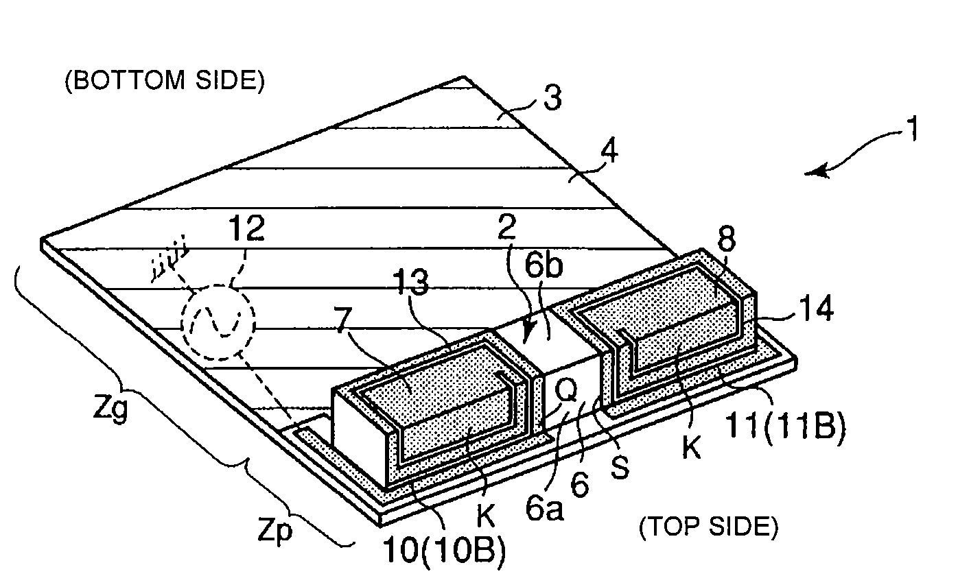
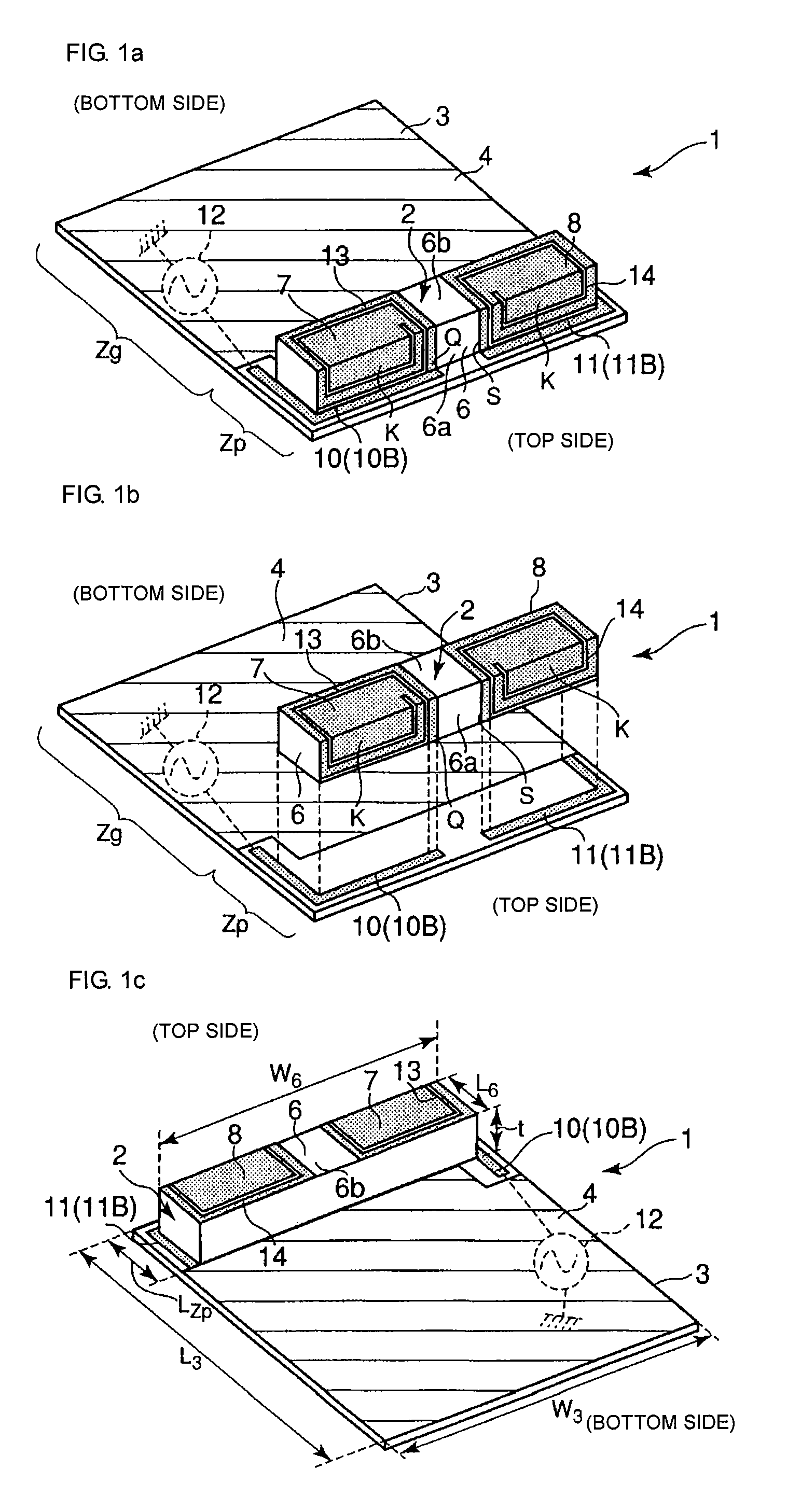
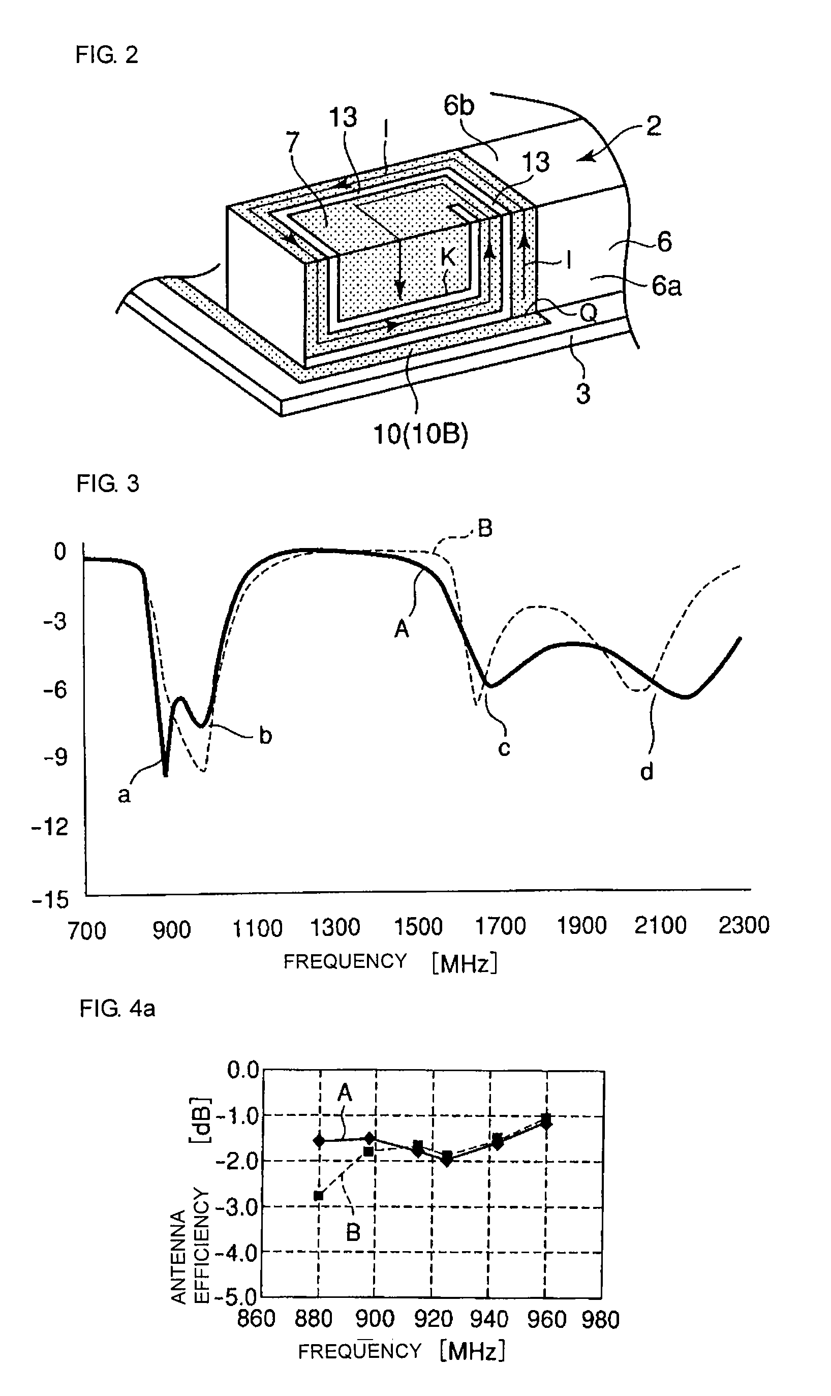
[0047]As shown by a schematic enlarged view of FIG. 2, the feed radiation electrode 7 of the antenna 2 forming the antenna structure 1 is provided on two surfaces, a side surface 6a near a top side and an upper surface 6b, of a dielectric base member 6. In the feed radiation electrode 7, a slit 13 is formed in two surfaces, the side surface 6a near the top side and the upper surface 6b, of the dielectric base member 6. Due to the formation of the slit 13 in the feed radiation electrode 7, a current path I of a fundamental mode is formed by extending from a feed end Q connected to a feed electrode 10 (10B) to an open end K via a looped path formed on the side surface 6a near the top side and the upper surface 6b of the dielectric base member 6.

[0048]In the first embodiment, the feed electrode 10 (10B) is provided in a non-ground region Zp of a circuit board 3 along the side surface 6a of the dielectric base member 6 near the top side and a left side surface of the dielectric base me...

second embodiment

[0070]In the second embodiment, since part of the antenna 2 (the feed radiation electrode 7 and the non-feed radiation electrode 8) protrudes from the non-ground region Zp of the circuit board 3 toward the outside of the board, compared with a case where the entire feed radiation electrode 7 and the non-feed radiation electrode 8 are provided within the non-ground region Zp, the space between the ground region Zg and each of the feed radiation electrode 7 and the non-feed radiation electrode 8 can be set apart by the amount of protrusion toward the outside the circuit board 3. Thus, since a negative effect of ground is reduced, an increase in the frequency bandwidth for radio communication and an improvement in the antenna efficiency can be achieved. Accordingly, a miniaturized and lower-profile antenna structure 1 can be achieved. In addition, miniaturization of a radio communication apparatus including the antenna structure 1 having such a configuration can be easily achieved.

[007...


PUM


Abstract

An antenna structure including a dielectric base member provided in a non-ground region of a circuit board and a feed radiation electrode provided on the dielectric base member. An outer side surface of the dielectric base member along an edge of one end of the circuit board defines a side surface. A feed electrode is provided in the non-ground region of the circuit board or outside the circuit board such that the feed electrode is disposed along side surfaces of the dielectric base member. One end of the feed radiation electrode defines a feed end connected to the feed electrode, and the other end of the feed radiation electrode defines an open end. The feed radiation electrode has a configuration in which a current path extending from the feed end to the open end has a loop shape so as to be provided on at least the side surface and an upper surface of the dielectric base member. A feed radiation electrode portion formed on the side surface of the dielectric base member 6 forms a capacitance between the feed radiation electrode portion and the feed electrode for improving antenna characteristics.

Description

CROSS REFERENCE TO RELATED APPLICATIONS[0001]The present application is a continuation of International Application No. PCT / JP2005 / 023639, filed Dec. 22, 2005, which claims priority to Japanese Patent Application No. JP2005-010589, filed Jan. 8, 2005, the entire contents of each of these applications being incorporated herein by reference in their entirety.FIELD OF THE INVENTION[0002]The present invention relates to an antenna structure provided in a radio communication apparatus, such as a portable telephone, and a radio communication apparatus including the same.BACKGROUND OF THE INVENTION[0003]FIG. 11a is a perspective view schematically showing an example of an antenna structure. FIG. 11b is an exploded view schematically showing the antenna structure. FIG. 11c shows the antenna structure shown in FIG. 11a when viewed from the bottom side. The antenna structure 1 includes an antenna 2. The antenna 2 is mounted in a non-ground region Zp of a circuit board 3. That is, a ground reg...

Claims


Application Information

Patent Timeline
Patent Type & Authority Patents(United States)
IPC IPC(8): H01Q1/24
CPCH01Q1/243H01Q1/38H01Q9/42
Inventor ONAKA, KENGOSATO, JINIZAWA, MASAHIRO
Owner MURATA MFG CO LTD
Why Eureka
Try Eureka