Planar inverted f antenna tapered type pifa with corrugation

Inactive Publication Date: 2007-06-14
ELECTRONICS & TELECOMM RES INST
View PDF15 Cites 10 Cited by
  • Summary
  • Abstract
  • Description
  • Claims
  • Application Information

AI Technical Summary

Benefits of technology

[0010] It is, therefore, an object of the present invention to provide a planar inverted F antenna for widening a frequency bandwidth by providing a linearly tap

Problems solved by technology

However, it is getting more complicated for designing the conventional planar inverted F antenna
Howev

Method used


Image

  • Planar inverted f antenna tapered type pifa with corrugation
  • Planar inverted f antenna tapered type pifa with corrugation
  • Planar inverted f antenna tapered type pifa with corrugation

Examples


Embodiment Construction

[0017] Hereinafter, a planar inverted F antenna in accordance with a preferred embodiment of the present invention will be described in more detail with reference to the accompanying drawings.

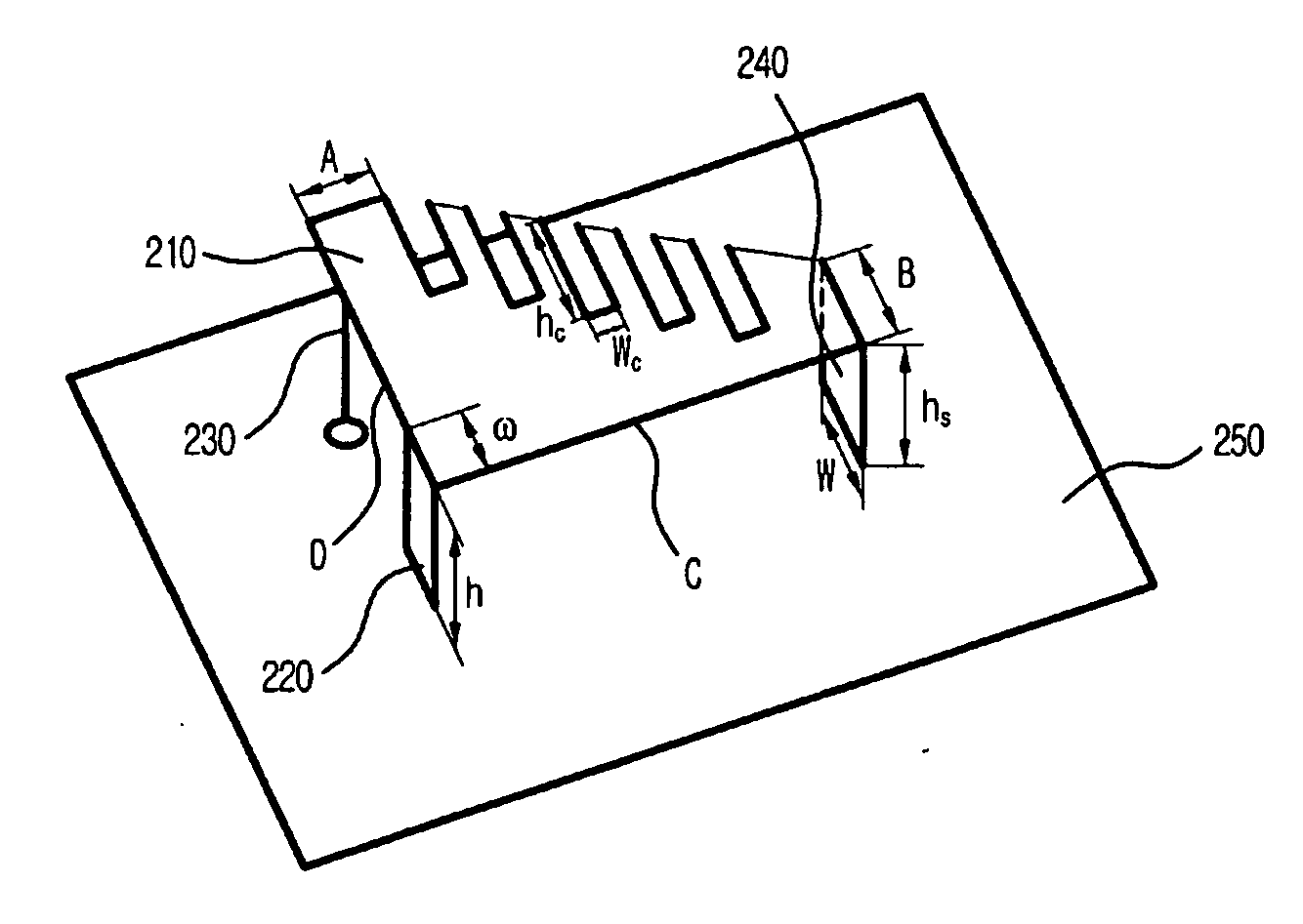
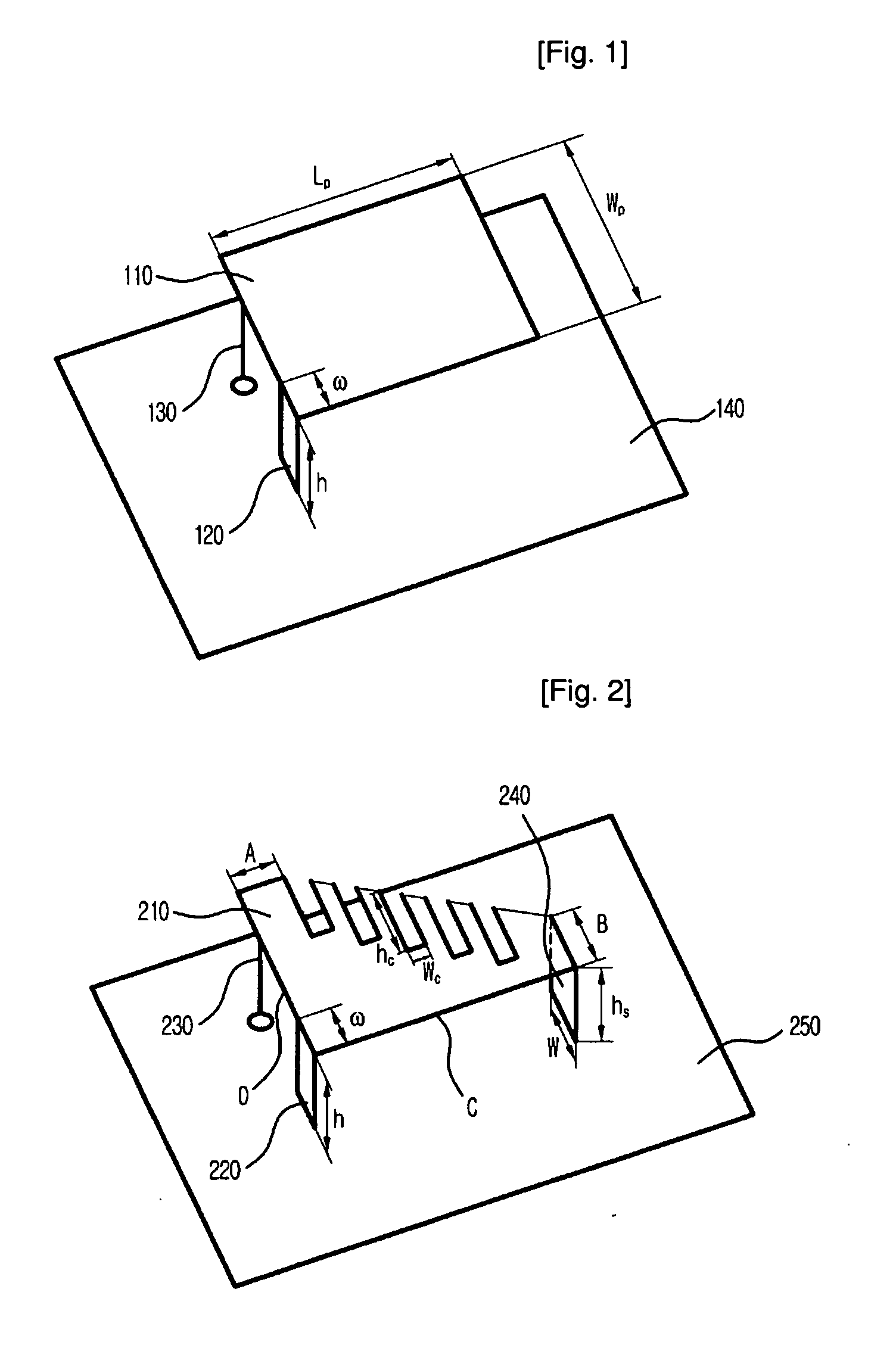
[0018]FIG. 2 is a diagram illustrating a planar inverted F antenna in accordance with a preferred embodiment of the present invention.

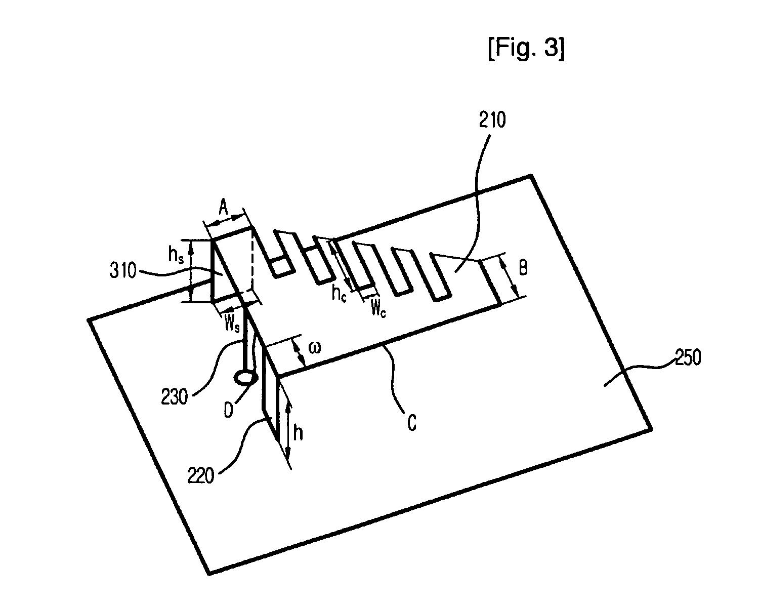
[0019] As shown in FIG. 2, the planar inverted F antenna 200 includes a radiation patch 210, an additional radiation patch 240, a shorting plate 220, a feeding line 230 and a grand plate 250.

[0020] The shorting plate 220 is equipped in between the ground plate 250 and the radiation patch 210. One side of the shorting plate 220 is coupled to the radiation patch 210 and other side of the shorting plate 220 is coupled to the ground pate 250. The shorting plate 220 has a function to short the radiation patch 210.

[0021] The feeding line 230 connected to the radiation patch 210 through the ground plate 250 has a function to supply electric power to the radiation pa...


PUM


Abstract

A planar inverted F antenna having a radiation patch having an asymmetric shape of linearly-tapered rectangle with a plurality of corrugated hollows is disclosed. The planar inverted F antenna having a radiation patch, includes: a first radiation patch for radiating a signal; a ground plate for grounding the first radiation patch; a feeding line for supplying an electric power to the first radiation patch; a short plate having one side coupled to the first radiation patch and other side coupled to the ground plate for shorting the first radiation patch, wherein the first radiation patch having an asymmetrical shape of linearly tapered rectangle and has one or more corrugated hollows.

Description

TECHNICAL FIELD [0001] The present invention relates to a radiation patch for a planar inverted F antenna; and, more particularly, to the radiation patch having an asymmetric shape of linearly-tapered rectangle with a plurality of corrugated hollows for a planar inverted F antenna in order to provide wide bandwidth characteristic. BACKGROUND ART [0002] A planar inverted F antenna is a modified microstrip antenna having a shape of inverted F. [0003]FIG. 1 is a diagram illustrating a conventional planar inverted F antenna in accordance with a prior art. [0004] Referring to FIG. 1, the conventional planar inverted F antenna 100 includes a rectangular radiation patch 110 having a size of a length Lp and width Wp, a shorting plate 120, a feeding line 130 and a ground plane 140. [0005] The shorting plate 120 is attached between the ground plane 140 and the rectangular radiation patch 110. The feeding line 130 supplies electric power to the rectangular radiation patch 110. [0006] The plana...

Claims


Application Information

Patent Timeline
IPC IPC(8): H01Q1/38H01Q9/04H01Q13/08
CPCH01Q9/0421H01Q9/0442H01Q13/08
Inventor KIM, BYUNG-CHANYUN, JE-HOONCHOI, HYUNG-DO
Owner ELECTRONICS & TELECOMM RES INST
Why Eureka
Try Eureka