Method and device for continuously measuring dynamic fluid consumption

A technology for measuring dynamics and consumption. It is applied in measurement devices, mass flow measurement devices, measurement capacity, etc., and can solve the problem that the measurement system is not an open system.

Inactive Publication Date: 2010-02-17
AVL LIST GMBH
View PDF0 Cites 12 Cited by
  • Summary
  • Abstract
  • Description
  • Claims
  • Application Information

AI Technical Summary

Problems solved by technology

However, such a mechanical pressure controller works like a "hydraulic diode", ie the flowing medium can only flow through the controller in one direction (ie downstream) and with the help of this The measurement system established by this pressure controller is not an open system
Costly pressure compensation in the event of fuel backflow from the injection system into the metering system or in the event of thermal expansion of the fuel

Method used


Image

  • Method and device for continuously measuring dynamic fluid consumption

Examples


Embodiment Construction

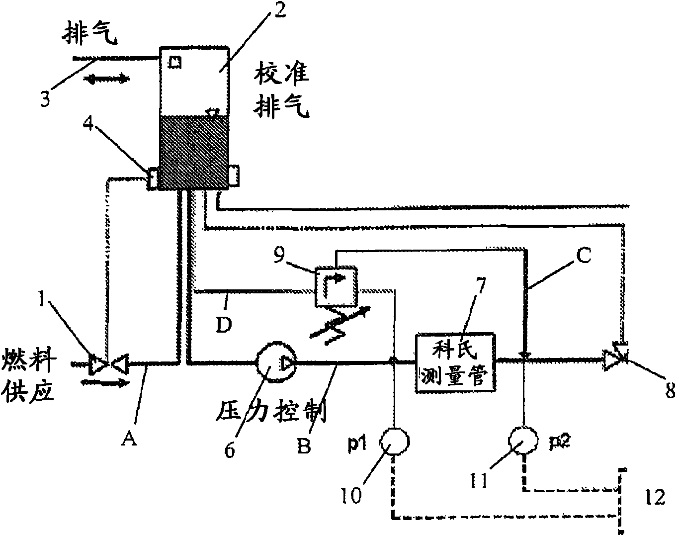
[0019] Via a line A and a filling valve 1 (preferably actuatable electromagnetically), a tank 2 as a storage container is supplied with liquid (ie fuel). The oil tank 2 also has a vent valve 3 and a liquid level sensor 4 connected to the filling valve 1 .

[0020] Fuel is fed from tank 2 via line B to a continuously operating flow sensor 7 , preferably a Coriolis sensor, by means of a preferably controllable fuel pump 6 . The fuel then preferably passes via the non-return valve 8 to an output location to which an engine as load (not shown) is connected and at which fuel with a predetermined specific pressure should be supplied.

[0021] A line C is tapped between the flow sensor 7 and the non-return valve 8 , which leads to a control input of, for example, a mechanical hydraulic pressure regulator 9 . The flow through line D, which is tapped off from line B between the fuel pump 6 and the flow sensor 7, is now regulated by the pressure regulator 9 depending on the pressure in...


PUM


Abstract

The invention relates to a method for continuously measuring dynamic fluid consumption, particularly fuel consumption, employing a continuously operating flow sensor (7) with variable pressure loss, preferably a mass flow sensor, wherein the pressure is determined downstream of the flow sensor (7) and used to control fluid conveyance. In order to enable continuous, accurate and temporally highly resolved consumption measurement and the highly dynamic determination of the flow rate, while maintaining the simplest design possible, at at least one time also the pressure directly upstream of the flow sensor (7), the difference of the two pressure values, and from this difference a value for the flow rate of the fluid are determined.

Description

technical field [0001] The invention relates to a method for continuously measuring dynamic fluid consumption, in particular fuel consumption, by means of a continuously operating flow sensor with variable pressure drop, preferably a mass flow sensor, wherein the determination The pressure downstream of said flow sensor and this pressure is used to control fluid delivery; the invention also relates to a device for continuous measurement of dynamic fluid consumption, in particular fuel consumption, said device comprising a fuel tank, possibly a regulating device , and preferably a controllable pump, a continuously operating flow sensor, preferably a Coriolis sensor, for the liquid, and a pressure sensor directly downstream of the flow sensor, the output of which is connected to, for example, a controllable pump connected to at least one control device for fluid flow. Background technique [0002] Discontinuously operating systems based on weighing (Waagen) are known for the ...

Claims


Application Information

Patent Timeline
Patent Type & Authority Applications(China)
IPC IPC(8): G01F1/34G01F1/50G01F1/84G01F15/02G05F7/00
CPCG01F9/008G01F1/34G01F9/023G01F15/022G05D7/00G01F1/50
Inventor K·考克M·塞纳斯卡
Owner AVL LIST GMBH
Why Eureka
Try Eureka