
Contact box and switching device

A switchgear and contact box technology, applied in the field of contact boxes, can solve problems such as uneven thickness of sealing insulators, product cracking, etc., and achieve the effects of compact structure, good environmental protection of materials, and improved product quality

Inactive Publication Date: 2016-12-07
HENAN SENYUAN ELECTRIC CO LTD
View PDF8 Cites 0 Cited by
  • Summary
  • Abstract
  • Description
  • Claims
  • Application Information

AI Technical Summary

Problems solved by technology

[0006] The purpose of the present invention is to provide a contact box, so as to solve the problem in the prior art that the sealing insulator of the contact box is uneven in thickness, which easily causes the product to crack

Method used


Image

  • Contact box and switching device

Examples


Embodiment

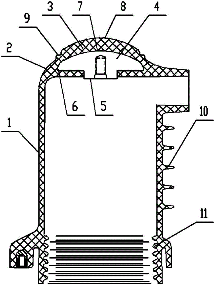
[0027] Embodiments of the contact box of the present invention, such as figure 1 As shown, it includes a cylindrical insulator 1 and a sealing insulator 3 connected to one end of the cylindrical insulator 1 through a transition shoulder 2, and the sealing insulator 3 is provided with a static contact installation insert 4; the static contact installation insert 4 is The umbrella handle 5 faces the mushroom-shaped structure of the cylindrical insulator 1, the outer edge 6 of the fixed contact installation insert extends to the transition shoulder 2, and the surface 7 of the side facing away from the cylindrical insulator 1 has a spherical structure.

[0028] The surface 8 of the sealing insulator 3 facing away from the cylindrical insulator 1 has a spherical structure, and the spherical structure of the sealing insulator is arranged concentrically with the spherical structure of the static contact mounting insert. The transition shoulder 2 has an annularly arranged stepped tran...


PUM


Abstract

The invention discloses a contact box and a switching device. The contact box comprises a cylindrical insulator and a sealing insulator connected with one end of the cylindrical insulator through a transition shoulder part. A static contact installation insert is arranged in the sealing insulator, and the outer edge of the static contact installation insert extends to the transition shoulder part. According to the contact box, the static contact installation insert and the sealing insulator are matched, so the thicknesses of all parts of the sealing insulator are basically equal, and the situation that a product cracks due to uneven thickness is avoided.

Description

technical field [0001] The invention belongs to the field of medium and high voltage switchgears, in particular to a contact box for 12kV complete switchgears. Background technique [0002] In the medium voltage switchgear, the use of the contact box has been very common, and the contact box mainly plays the role of insulation isolation and connection transition. [0003] At present, the box body material of the contact box is thermosetting epoxy resin material, which is formed by automatic pressure gel (APG) process. This process requires a lot of materials, the finished product is heavy, the production efficiency is low, and the product is easy to be damaged; the post-curing time of thermosetting epoxy resin material is long and the energy consumption is large, the production site is easy to be dirty and difficult to clean, and the waste materials cannot be recycled. It is difficult to degrade under natural conditions and causes great pollution to the natural environment....

Claims


Application Information

Patent Timeline
Patent Type & Authority Applications(China)
IPC IPC(8): H02B1/14H02B1/30
CPCH02B1/14H02B1/30
Inventor 李小兰袁钤亚
Owner HENAN SENYUAN ELECTRIC CO LTD
Learn More