Full-automatic rice seedling throwing device

A fully automatic rice paddy technology, applied in planting methods, applications, agriculture, etc., can solve the problems of no seedlings, more than one seedling in some places, easy damage to the roots of seedlings, and heavy workload of farmers. The effect of fewer people operating and low labor intensity

Inactive Publication Date: 2016-12-14
罗忠良
View PDF6 Cites 3 Cited by
  • Summary
  • Abstract
  • Description
  • Claims
  • Application Information

AI Technical Summary

Problems solved by technology

There are several disadvantages in this rice seedling throwing device: the one is that the farmers' workload is relatively large
Because it is necessary to manually pull out the seedlings on the seedling tray and put them on the seedling transport belt, the farmers have a large workload
Second, there are many people engaged in throwing rice seedlings
The third is that when the seedling hook is working, it hooks the roots of the seedlings and hooks the seedlings out of the seedling bucket. The sharp and hard seedling hooks are easy to damage the roots of the seedlings. During work, the roots of some seedlings are damaged, and the roots are damaged. After the damaged seedlings are thrown into the paddy field, they cannot survive, and it will take a few days before the dead seedlings can be found. For the dead seedlings, it is necessary to manually replant the seedlings
The fourth is that the hook bar is working, sometimes it does not hook the seedlings, sometimes it hooks two or more rice shoots, resulting in rice shoots thrown into the paddy field, some places have no rice shoots, and some places have more than one bunch of rice shoots. Manual adjustment and replanting of seedlings are required

Method used


Image

  • Full-automatic rice seedling throwing device
  • Full-automatic rice seedling throwing device
  • Full-automatic rice seedling throwing device

Examples


Embodiment Construction

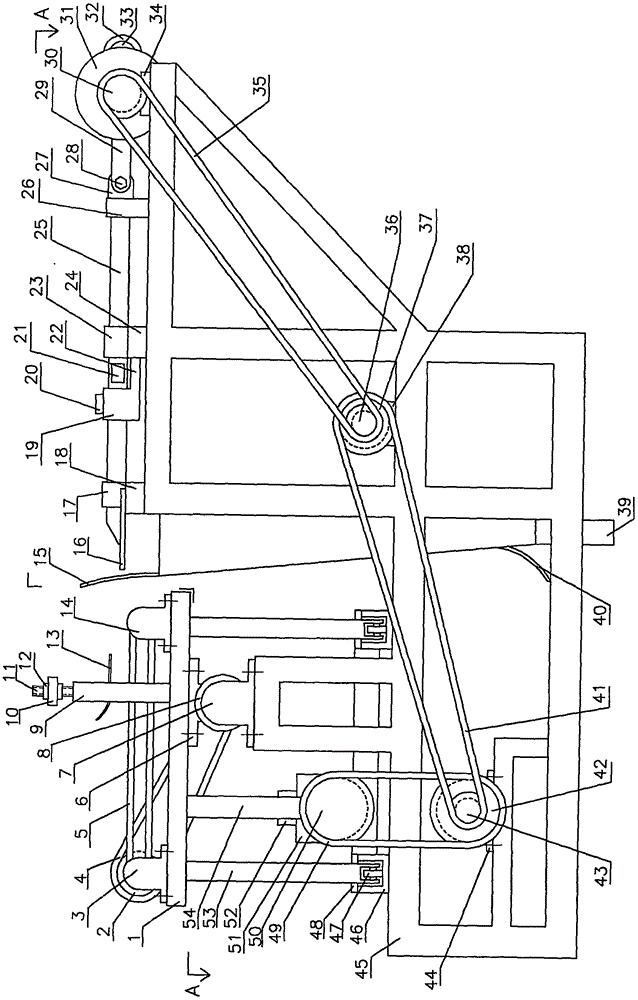
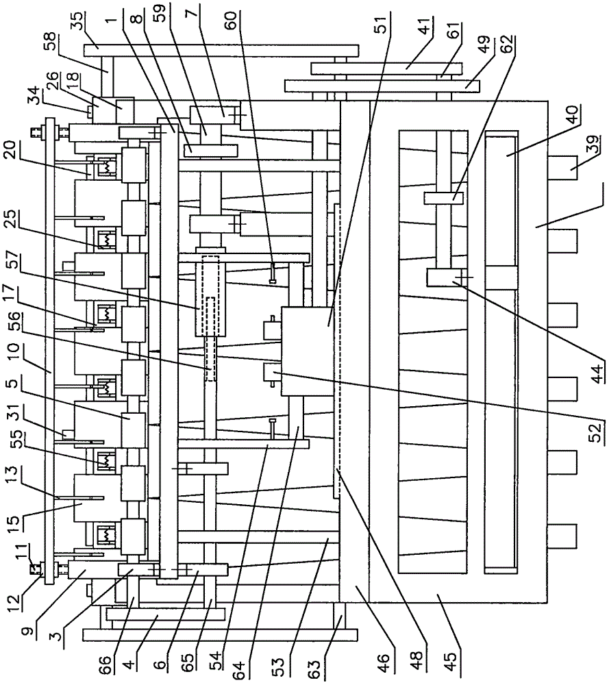
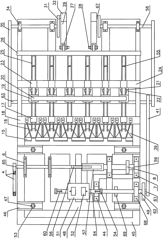
[0037] exist figure 1 , figure 2 , image 3 In the shown embodiment, one group of seedling bucket 39 is welded on the middle part of support 45, and two U-shaped grooves 46 are arranged on the support 45, and the middle part of every U-shaped groove 46 has U-shaped groove cover plate 48, described The U-shaped groove cover plate 48 is used to limit the movement range of the support foot 53 in the U-shaped groove 46 . The conveying plate 1 is supported by four legs 53 , the lower end of each leg 53 is connected with a wheel 47 , and the lower end of the legs 53 and the wheel 47 are placed in the U-shaped groove 46 .

[0038]Shuttle 51, two travel switches 52 are installed on this seedling throwing device, and one end of shuttle rotating shaft 62 stretches in the shuttle, and the other end of shuttle rotating shaft 62 is connected with the bearing sleeve in the shuttle shaft bearing block 68, reciprocating Device driving gear 50 is installed on the reciprocating device rotat...


PUM


Abstract

The invention discloses a full-automatic rice seedling throwing device. A group of seedling buckets are welded in the middle of a support, the lower ends of the seedling buckets penetrate a support bottom plate, two U-shaped grooves are welded on the support, a conveying plate is supported by four support legs, the lower end of each support leg is connected with a wheel, two ends of a connecting rod are connected with the conveying plate and a reciprocating device translation shaft respectively, a left straight beam and a right straight beam are mounted on the support, a group of left fixing clamp sleeves and right fixing clamp sleeves are mounted on the left straight beam and the right straight beam respectively, a movable sleeve top plate is arranged at the lower end of a movable clamp sleeve, two sides of the middle of each clamp are respectively provided with a top block, a spring is mounted on the right of each clamp, the right ends of one group of clamps are connected with a sliding beam, two hangers are arranged in the middle of the right of the sliding beam, a bearing sleeve is arranged at the right end of the connecting rod and connected with a cylindrical rod through a bearing, the left end of the connecting rod is connected with the hangers through screws, a gear shaft sleeve is arranged at the rear end of a seedling feeding driving shaft, and a gear shaft is arranged at the front end of a seedling feeding driven shaft and connected with the gear shaft sleeve in a sleeving manner.

Description

Technical field [0001] The invention relates to a fully automatic rice seedling throwing device. Background technique [0002] At present, paddy rice seedling cultivation is to be finished on the seedling tray, and the seedling tray has evenly distributed hole holes, and the nutrient mud and grain seeds are placed in the hole holes, and after growing into seedlings, the rice shoots on the seedling tray are pulled out (the roots of the rice shoots Bring out the nutrient mud) and throw it into the paddy field. [0003] Known rice seedling throwing method: one is that the farmers use their hands to pull out the seedlings from the seedling tray and throw them into the field. In this method of throwing seedlings, the distribution of the seedlings in the field is extremely uneven, and it is necessary to manually replant and adjust the seedlings thrown into the field. , resulting in low work efficiency and high labor intensity for farmers. Another kind is to use rice seedling thr...

Claims


Application Information

Patent Timeline
Patent Type & Authority Applications(China)
IPC IPC(8): A01C11/00
CPCA01C11/003
Inventor 罗忠良
Owner 罗忠良
Why Eureka
Try Eureka