Device and method for generating aerosol

An aerosol generation and aerosol technology, which is applied in the field of electronic cigarettes, can solve the problems of carbonization of liquid penetrating parts, low liquid conduction rate of liquid penetrating parts, and high temperature of electric heating body, and achieves the effect of avoiding carbonization

Active Publication Date: 2016-12-14
SHANGHAI TOBACCO GRP CO LTD
View PDF9 Cites 12 Cited by
  • Summary
  • Abstract
  • Description
  • Claims
  • Application Information

AI Technical Summary

Problems solved by technology

[0005] However, there are disadvantages in this patent: the liquid penetrating part in the atomizing core assembly is directly placed on the electric heating body, and the electric heating body is not wound on the penetrating part. Although the possibility of carbonization in the case of overheating of the electric heating body is reduced, However, since the periphery of the electric heating body is in contact with the liquid penetrating part, the liquid conduction rate of the liquid penetrating part is low in practical applications, and the temperature of the electric heating body is still too high, resulting in carbonization of the part of the liquid penetrating part

Method used


Image

  • Device and method for generating aerosol
  • Device and method for generating aerosol

Examples


Embodiment 1

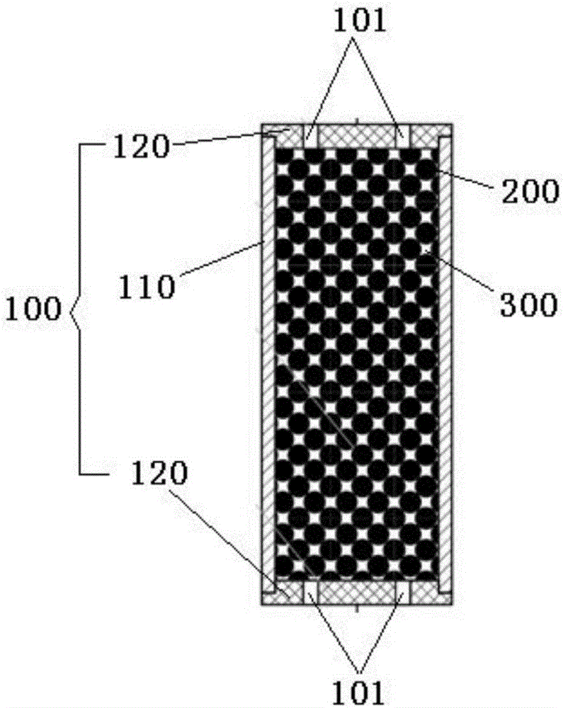
[0033] Such as figure 1 As shown, the aerosol generating device of the present embodiment includes:

[0034] The casing 100, the casing 100 is a hollow structure, and the casing 100 is provided with a ventilation hole 101;

[0035] The housing 100 includes a housing body 110 and at least two conductors 120 spaced apart on the housing body 110;

[0036] A plurality of conductive particles 200 are filled inside the casing 100, adjacent conductive particles 200 are in contact with each other, and the conductor 120 is in contact with at least one conductive particle 200;

[0037] The aerosol matrix 300 is filled inside the casing 100 , and the aerosol matrix 300 is in contact with the plurality of conductive particles 200 .

[0038] When the aerosol generating device of this embodiment is in use, after a voltage is applied to the conductor 120, an electric current passing through a plurality of conductive particles 200 is generated, and the electric current causes the plurality ...

Embodiment 2

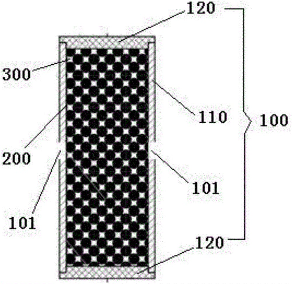
[0053] like figure 2 As shown, the difference between this embodiment and Embodiment 1 is that: the vent hole 101 is arranged on the shell body 110. In this embodiment, there are two vent holes 101, and the two vent holes 101 are arranged coaxially so as to facilitate the airflow to drive The aerosol is released to the outside of the housing 100 .

[0054] The conductive particles 200 in this embodiment are modified graphite particles, and the properties of the modified graphite particles are stable, which can avoid the problem of unstable heating of the conductive particles 200 to the aerosol matrix 300 .

[0055] The aerosol generating device and the aerosol generating method of the present invention use a plurality of conductive particles 200 as heating elements, the plurality of conductive particles 200 are distributed inside the housing 100, the aerosol matrix 300 contacts the surface of the conductive particles 200, and after electrification The heat of the conductive ...


PUM


Abstract

The invention provides a device and a method for generating aerosol. The device comprises a shell, a plurality of conductive particles and aerosol matrixes. The shell is of a hollow structure, and air holes are formed in the shell; the shell comprises a shell body and at least two conductors, and the conductors are arranged on the shell body at intervals; the shell is filled with the conductive particles, the adjacent conductive particles are in contact with one another, and each conductor is in contact with at least one conductive particle; the shell is filled with the aerosol matrixes, and the aerosol matrixes are in contact with the multiple conductive particles. The device and the method have the advantages that the multiple conductive particles are used as heating elements and are distributed inside the shell, the aerosol matrixes are in contact with the surfaces of the conductive particles, can be uniformly and stably heated by heat generated by the electrified conductive particles and can be heated and atomized to obtain the aerosol, the aerosol can be released via the air holes, and accordingly the aerosol matrixes can be effectively prevented from being carbonized in heating procedures.

Description

technical field [0001] The invention relates to the field of electronic cigarettes, in particular to an aerosol generating device and an aerosol generating method. Background technique [0002] The aerosol generating device is a kind of appliance that has broad promotion prospects and can replace traditional cigarette products. Most aerosol generating devices use heated liquid to evaporate to produce a mist similar to cigarette smoke. The liquid contains nicotine as an active ingredient, which allows consumers to enjoy the process of simulating cigarette smoking. [0003] At present, the internal structure adopted by most aerosol generating devices at home and abroad, especially the internal structure of the heating part is roughly the same. The structure adopted is that the electric heating wire is wound on the glass fiber rope, and the liquid is transferred from the liquid cavity or the glass fiber rope through the penetration of the glass fiber rope. The part of the liqu...

Claims


Application Information

Patent Timeline
Patent Type & Authority Applications(China)
IPC IPC(8): A24F47/00
Inventor 陈超李祥林郑爱群
Owner SHANGHAI TOBACCO GRP CO LTD
Why Eureka
Try Eureka