Distraction compression clamp for minimally invasive spine surgery

A technique of minimally invasive surgery and spine, applied in the field of medical equipment, can solve the problems of enlarging the incision, not being suitable for minimally invasive surgery, and not being able to meet the requirements of minimally invasive surgery, minimally invasive surgery, angular braces or pressurization, etc., to achieve Ease of use and simple operation

Inactive Publication Date: 2016-12-14
CHUANGHUI MEDICAL EQUIP JIANGSU
View PDF10 Cites 6 Cited by
  • Summary
  • Abstract
  • Description
  • Claims
  • Application Information

AI Technical Summary

Problems solved by technology

Chinese patents CN201320855790.2 and CN201320855796.X respectively disclose a pressurized forceps and spreader forceps, but these two tools are not suitable for minimally invasive surgery, and two tools are required to complete the spreader and pressurization
Chinese patent CN201420388096.9 discloses a minimally invasive percutaneous spinal distractor. The tool is inserted into the in

Method used


Image

  • Distraction compression clamp for minimally invasive spine surgery
  • Distraction compression clamp for minimally invasive spine surgery
  • Distraction compression clamp for minimally invasive spine surgery

Examples


Embodiment 1

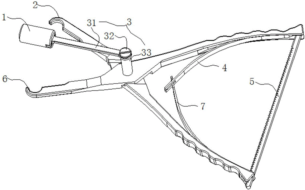
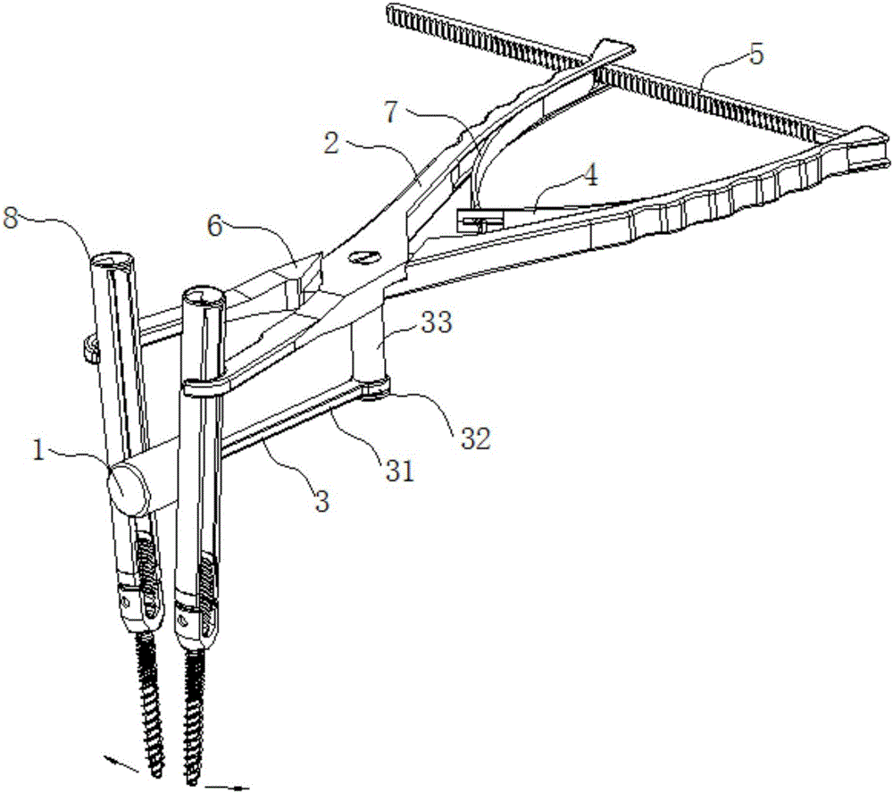
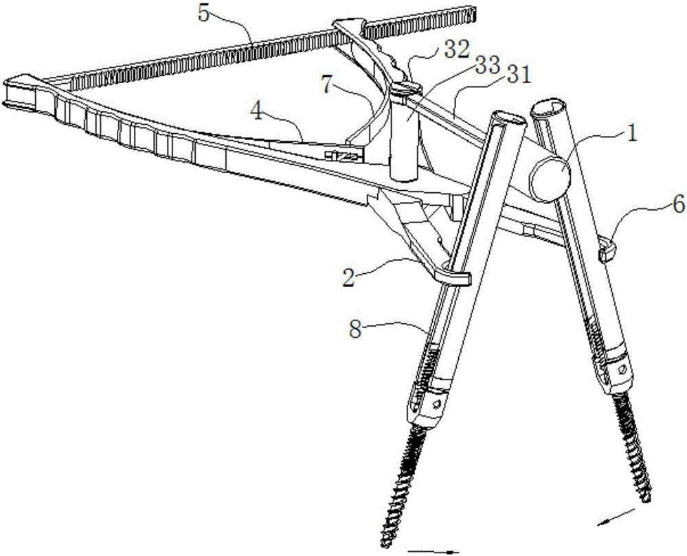
[0018] See Figure 1 to Figure 3 , the present invention is a spreader compression forceps for spinal minimally invasive surgery, which has a left forceps handle 6, a right forceps handle 2, a fulcrum 1, a connecting device 3 and a fixing device 5; the left forceps handle 6 and the right forceps handle 2 are connected by The device 3 is connected in an "X" shape and can be rotated around the connecting device 3. The front end of the left pliers 6 handle and the front end of the right pliers handle 2 both have gripping parts, the rear ends of both have a pressing part, and the rear end part It is connected by a fixing device 5;

[0019] The connecting device 3 includes a connecting rod 31 , a screw 32 and a connecting sleeve 33 ;

[0020] The fixing device 5 is a rack or a screw with a nut.

[0021] The rear end of the left pliers handle 6 and the rear end of the right pliers handle 2 are respectively correspondingly and fixedly connected with one end of the right elastic pie...


PUM


Abstract

The invention relates to a distraction compression clamp for minimally invasive spine surgery. The compression clamp comprises a left clamping handle, a right clamping handle, a fulcrum, a connecting device and a fixing device, wherein the left clamping handle and the right clamping handle are connected in an X-shape by virtue of the connecting device, and can rotate around the connecting device; a holding part is respectively arranged at the front end of the left clamping handle and the front end of the right clamping handle, and a grasp part is respectively arranged at the rear end of the left clamping handle and the rear end of the right clamping handle; one end of the fixing device is fixedly connected with the rear end part of the left clamping handle, and the other end of the fixing device is blocked to the rear end part of the right clamping handle. The distraction compression clamp can perform angular distraction and compression operations on the vertebral body with a minimally invasive pedicle screw under the condition of not enlarging an existing cut.

Description

technical field [0001] The invention relates to the technical field of medical instruments, in particular to a distraction and compression forceps for spinal minimally invasive surgery. Background technique [0002] Minimally invasive spine surgery is more and more favored by patients and doctors because of its small surgical incision, small tissue trauma, less blood loss, and quick postoperative recovery. In minimally invasive spine surgery, the patient's spinal segment is often distracted or compressed. In open surgery, distraction or compression is accomplished by distracting or compressing the pedicle screw with distractor or compression forceps. Chinese patents CN201320855790.2 and CN201320855796.X respectively disclose a compression forceps and a spreader forceps, but these two tools are not suitable for minimally invasive surgery, and two tools are required for expansion and pressure. Chinese patent CN201420388096.9 discloses a minimally invasive percutaneous spinal...

Claims


Application Information

Patent Timeline
IPC IPC(8): A61B17/02
CPCA61B17/025A61B17/0206A61B17/0218A61B2017/0256
Inventor 徐文利蔡勇
Owner CHUANGHUI MEDICAL EQUIP JIANGSU
Why Eureka
Try Eureka