Welding device

A welding device and driving device technology, applied in welding equipment, metal processing equipment, manufacturing tools, etc., can solve the problems of low welding efficiency and low welding quality of products, and achieve the effect of improved consistency

Inactive Publication Date: 2016-12-14
惠州市益柏科技有限公司
View PDF0 Cites 2 Cited by
  • Summary
  • Abstract
  • Description
  • Claims
  • Application Information

AI Technical Summary

Problems solved by technology

[0003] The problem to be solved by the present invention is the problem of

Method used


Image

  • Welding device
  • Welding device

Examples


Embodiment Construction

[0017] In order to enable those skilled in the art to better understand the present invention, the present invention will be further described below in conjunction with the embodiments and accompanying drawings.

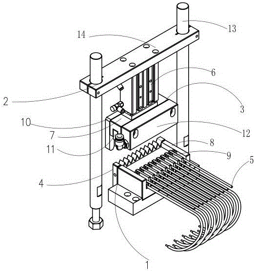
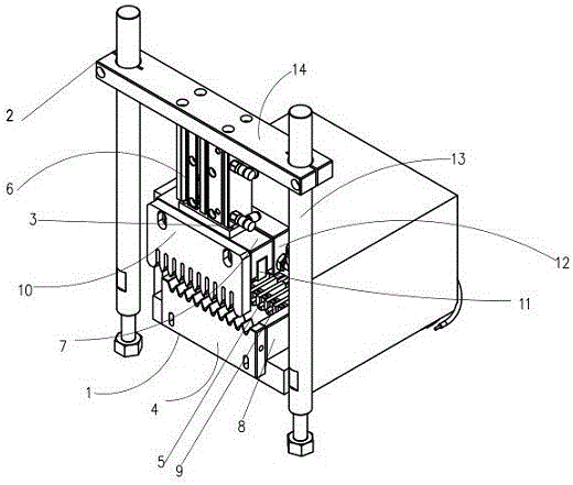
[0018] Such as figure 1 and figure 2 As shown, in a preferred embodiment, a welding device mainly includes a base, a bracket 2 fixed on the base, a pressing mechanism 3 and a welding mechanism 1 .

[0019] Wherein, the bracket 2 mainly includes two upright fixed rods 13 fixed on the base and a horizontally arranged fixed plate 14 fixed on the upper end of the fixed rods, the lower part of the fixed plate is connected with the pressing mechanism 3 . The pressing mechanism 3 mainly includes a speed-adjustable cylinder, a U-shaped fixed block 7 that moves up and down under the action of the cylinder, a downward pressure guide block 10 and an inert gas assembly plate 12 . The U-shaped bottom of the fixed block 7 is connected to the end of the cylinder rod of the cylin...


PUM


Abstract

The invention discloses a welding device. The welding device comprises a welding mechanism, a bracket, and a pressing mechanism fixed on the bracket; the welding mechanism includes a plate-shaped welding ground electrode and multiple welding electrode needles; multiple guide grooves are formed in one end, towards the pressing mechanism, of the welding ground electrode; the multiple welding electrode needles are arranged on one side of the welding ground electrode, and are opposite to sawtooth-shaped guide grooves one to one; and the pressing mechanism includes a driving device fixed on the bracket, and a fixed block fixed on the driving device and capable of moving up and down under driving of the driving device. The welding device realizes the function of synchronously welding multiple products, improves the welding efficiency, and prevents bad welding quality caused by nonuniform welding in joints of welded products.

Description

technical field [0001] The invention relates to the technical field of welding, in particular to a welding device. Background technique [0002] Welding technology, as a traditional craft and technology in the manufacturing industry, has developed very rapidly in recent years in industrial applications. Most of the traditional welding is manual welding. Due to the greater influence of human factors and poor controllability, the final product The welding quality is low, the welding efficiency is low, and the welded products cannot meet the quality requirements. In the field of industrial automation, many enterprises have a very urgent demand for advanced welding equipment. Contents of the invention [0003] The problem to be solved by the invention is the problems of low welding efficiency and low welding quality of products in the prior art. [0004] In order to solve the above-mentioned technical problems, the present invention adopts the following technical schemes to a...

Claims


Application Information

Patent Timeline
IPC IPC(8): B23K31/02
CPCB23K31/02
Inventor 陶伟荣
Owner 惠州市益柏科技有限公司
Why Eureka
Try Eureka