Supercharge Your Innovation With Domain-Expert AI Agents!

Reciprocating material poking device

A reciprocating and mounting frame technology, which is applied in the field of reciprocating material shifting devices, can solve problems such as slow movement, long transportation time, and complex structure.

Inactive Publication Date: 2016-12-14
SHANDONG IRON & STEEL CO LTD
View PDF6 Cites 0 Cited by
  • Summary
  • Abstract
  • Description
  • Claims
  • Application Information

AI Technical Summary

Problems solved by technology

[0002] At present, the devices for collecting materials (such as collecting steel bars) include chain conveying, belt conveying and rectangular movement forms. These structural forms generally have defects such as complex structure, large space occupation, too slow movement form, and long transportation time. This is Weaknesses of existing technology

Method used


Image

  • Reciprocating material poking device
  • Reciprocating material poking device
  • Reciprocating material poking device

Examples


Embodiment Construction

[0018] In order to clearly illustrate the technical characteristics of this solution, the following will describe this solution through specific implementation modes and in conjunction with the accompanying drawings.

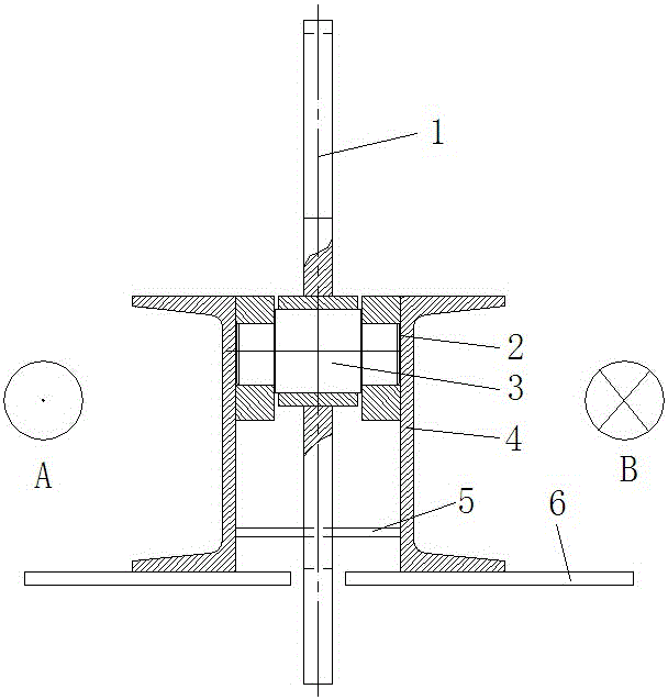
[0019] Direction A: the outward direction perpendicular to the paper surface; Direction B: the inward direction perpendicular to the paper surface.

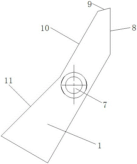
[0020] A kind of reciprocating material shifting device, as shown in the figure, it comprises movable base 6, is fixedly connected with installation frame 4 on described movable base 6, and the top of described installation frame 4 is hinged with finger 1, and the lower part is fixedly connected (such as Welding) There is a horizontal arm 5 for limiting the lower part of the claw 1. The claw 1 is a special-shaped plate, and the middle part of the claw 1 is provided with a hinged hole 7 along its thickness direction. The center line of the hinged hole 7 and the movable base The running direction of 6 is vertical. T...


PUM


Abstract

The invention provides a reciprocating material poking device which comprises a movable base. A mounting rack is fixedly connected to the movable base. A poking claw is hinged to the upper portion of the mounting rack. The lower portion of the mounting rack is fixedly connected with a horizontal stop arm used for limiting the lower portion of the poking claw. The poking claw is a special-shaped plate. A hinge hole is formed in the middle of the poking claw in the thickness direction of the poking claw. The weight of the part, located on the lower portion of the center line of the hinge hole, of the poking claw is larger than that of the part, located on the upper portion of the center line, of the poking claw. The bottom end of the poking claw is lower than the lower end of the horizontal stop arm. The side, located on the horizontal stop arm, of the poking claw is provided with a limiting face A and a limiting face B which are sequentially connected. A guide face A and a guide face B which are sequentially connected are arranged above the poking claw. After the structural form is adopted, when the movable base does reciprocating motion in the direction perpendicular to the paper face, the poking claw can rotate within the limited range under the limit of the horizontal stop arm to carry out material collecting, and the reciprocating material poking device is simple in structure and small in occupied space.

Description

technical field [0001] The invention relates to a feeding device, in particular to a reciprocating feeding device. Background technique [0002] At present, the devices for collecting materials (such as collecting steel bars) include chain conveying, belt conveying and rectangular movement forms. These structural forms generally have defects such as complex structure, large space occupation, too slow movement form, and long transportation time. This is The deficiencies in the prior art. Contents of the invention [0003] The technical problem to be solved by the present invention is to provide a reciprocating material shifting device aiming at the shortcomings of the prior art, which has a simple structure, small space occupation and high operating efficiency. [0004] This solution is achieved through the following technical measures: the reciprocating material shifting device includes a movable base, a mounting frame is fixedly connected to the movable base, the upper p...

Claims


Application Information

Patent Timeline
IPC IPC(8): B65G25/08
CPCB65G25/08
Inventor 赵建彪田成李柏君
Owner SHANDONG IRON & STEEL CO LTD
Features
  • R&D
  • Intellectual Property
  • Life Sciences
  • Materials
  • Tech Scout
  • Unparalleled Data Quality
  • Higher Quality Content
  • 60% Fewer Hallucinations
Learn More