
Blow-type vacuum suction cup and vacuum adsorption equipment with the blow-type vacuum suction cup

A vacuum suction cup and vacuum adsorption technology, applied in the direction of conveyor objects, transportation and packaging, etc., can solve the problems of large investment, high use and maintenance costs, low efficiency of vacuum machines, etc., to achieve reduced initial investment, reliable performance, and smooth surface Effect

Active Publication Date: 2018-04-17
JIANGSU POLYTECHNIC COLLEGE OF AGRI & FORESTRY
View PDF5 Cites 0 Cited by
  • Summary
  • Abstract
  • Description
  • Claims
  • Application Information

AI Technical Summary

Problems solved by technology

However, this kind of vacuum suction cup has a large initial investment, the efficiency of the vacuum machine is low, and the high cost of use and maintenance limits its further application.

Method used


Image

  • Blow-type vacuum suction cup and vacuum adsorption equipment with the blow-type vacuum suction cup
  • Blow-type vacuum suction cup and vacuum adsorption equipment with the blow-type vacuum suction cup
  • Blow-type vacuum suction cup and vacuum adsorption equipment with the blow-type vacuum suction cup

Examples


Embodiment Construction

[0039] Below in conjunction with specific embodiment, further illustrate the present invention, should be understood that these embodiments are only used to illustrate the present invention and are not intended to limit the scope of the present invention, after having read the present invention, those skilled in the art will understand various equivalent forms of the present invention All modifications fall within the scope defined by the appended claims of the present application.

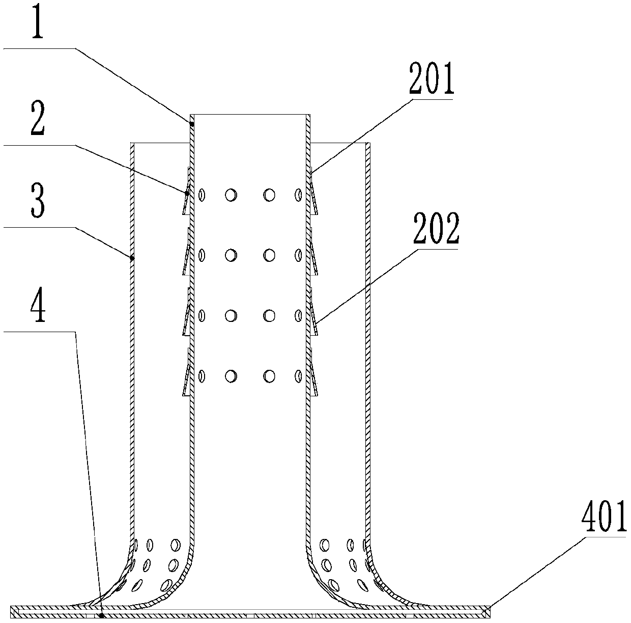
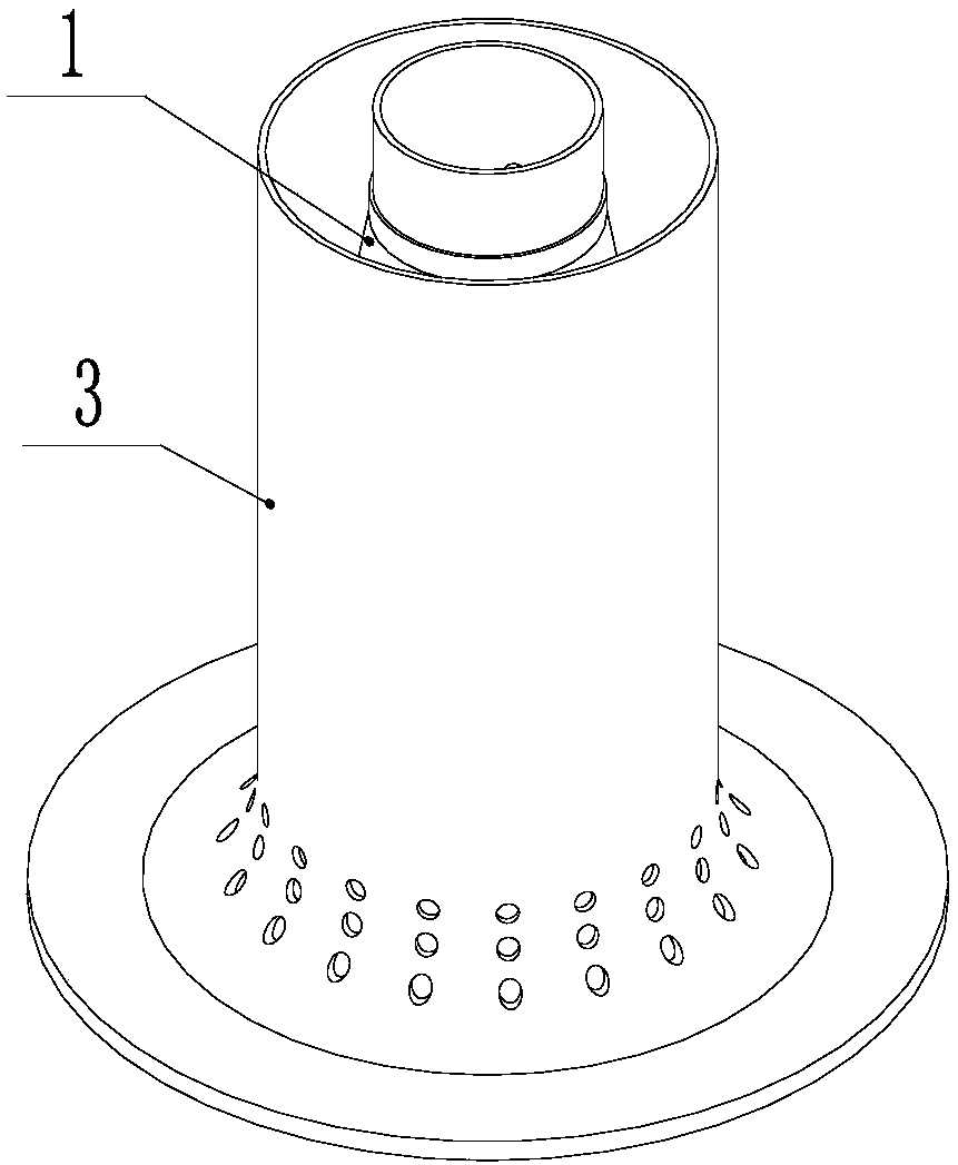
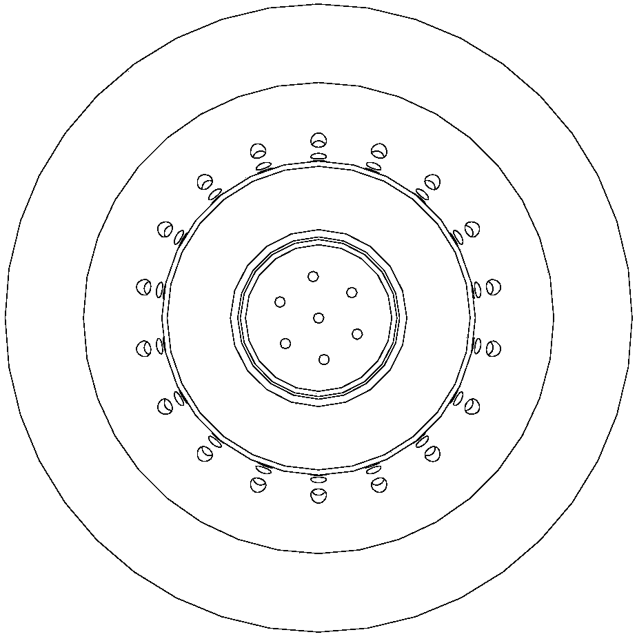
[0040] Such as Figure 1~3 As shown, the air blowing vacuum chuck of the present invention includes an inner cylinder 1 , a one-way seal 2 , an outer cylinder 3 and a suction disk 4 .

[0041] combine Figure 4 , the inner cylinder 1 includes a first straight cylinder section 101 and a first flared section 102 connected to the bottom of the first straight cylinder section, and the first straight cylinder section 101 and the first flared section 102 are integrally formed. The side wall of the fir...


PUM


Abstract

The invention discloses an air blowing type vacuum sucking disc and a vacuum adsorption device with the air blowing type vacuum sucking disc. The air blowing type vacuum sucking disc comprises an inner barrel, an adsorption disc which is arranged at the bottom of the inner barrel and covers an opening in the bottom of the inner barrel, and an outer barrel which is arranged outside the inner barrel in a sleeving manner, wherein negative pressure holes are formed in the side wall of the inner barrel; the inner barrel is provided with unidirectional sealing elements used for unidirectionally sealing the negative pressure holes; the unidirectional sealing elements prevent airflow from flowing from the outer side of the inner barrel into the inner barrel through the negative pressure holes; the adsorption disc is provided with suction holes; exhaust holes are formed in the side wall of the outer barrel; the exhaust holes are positioned below the negative pressure holes; and the bottom of the outer barrel and the bottom of the inner barrel are hermetically connected. According to the novel-structure vacuum sucking disc provided by the invention, ordinary vacuum sucking discs are made vacuum through extracting air with a vacuum machine; and in the air blowing type vacuum sucking disc, an air compressor is adopted to generate compressed air, the compressed air flows directionally at a high speed, and a vacuum state is achieved, namely, the vacuum state is achieved through adopting an air blowing method.

Description

technical field [0001] The invention relates to a vacuum suction cup, in particular to an air-blowing vacuum suction cup and vacuum adsorption equipment with the air-blowing vacuum suction cup. Background technique [0002] Suction cup is a very common equipment in industrial production and daily life. A vacuum chuck is a device that maintains the attachment of two objects without separation through vacuum. In the industry, the actions of "holding" and "putting" in the process of handling and migration are realized by changing the vacuum degree of the suction cup. With the control system, the automation of the production process can be realized. [0003] Industrial vacuum suction cups generally use a vacuum machine to suck out the air in the suction cup to form a vacuum negative pressure. When the object to be transported is in close contact with the suction cup, the vacuum negative pressure generated by the vacuum machine makes the object to be transported and the suction...

Claims


Application Information

Patent Timeline
Patent Type & Authority Patents(China)
IPC IPC(8): B65G47/91
CPCB65G47/91
Inventor 贾小伟张丽丽
Owner JIANGSU POLYTECHNIC COLLEGE OF AGRI & FORESTRY
Learn More