Eureka AIR delivers breakthrough ideas for toughest innovation challenges, trusted by R&D personnel around the world.

High speed carding machine

A carding machine, high-speed technology, used in fiber processing, deburring devices, textiles and papermaking, etc., can solve the problems of increased CV output, inability to achieve airflow resolution, inability to achieve, etc., to reduce carding loops and improve laying. Net quality, the effect of reducing the CV value

Active Publication Date: 2018-06-22
JIANGSU YINGYANG NONWOVEN MASCH CO LTD
View PDF18 Cites 2 Cited by
  • Summary
  • Abstract
  • Description
  • Claims
  • Application Information

AI Technical Summary

Problems solved by technology

[0005] However, the above-mentioned measures of setting windshield rollers or windshields cannot meet the expectations of the industry, because no matter whether the windshield rollers or windshields only play the role of avoiding the formation of airflow vortices in the triangular area as much as possible, they cannot Dissolving the air flow in this part (that is, the area of ​​the aforementioned triangular area) and even forming negative pressure in the triangular area is therefore a measure to treat the surface rather than the root cause
Especially, when the working speed of the carding machine is high, that is, under the adjustment of the carding state, the effect of the aforementioned windshield roller or windshield is better than nothing, and seriously affects the cotton output efficiency of the cotton roller, because under the action of the airflow vortex , it will make the fiber that should have entered the cotton outlet roller return to the main carding roller after carding, so that the carding ring will increase, and the CV (non-uniform rate) value of the outlet network will increase, that is, the outlet rate will decrease.

Method used


Image

  • High speed carding machine
  • High speed carding machine

Examples


Embodiment Construction

[0021] In order to understand the technical essence and beneficial effects of the present invention more clearly, the applicant will describe in detail the following examples, but the descriptions of the examples are not intended to limit the solutions of the present invention. Equivalent transformations that are only formal but not substantive should be regarded as the scope of the technical solution of the present invention.

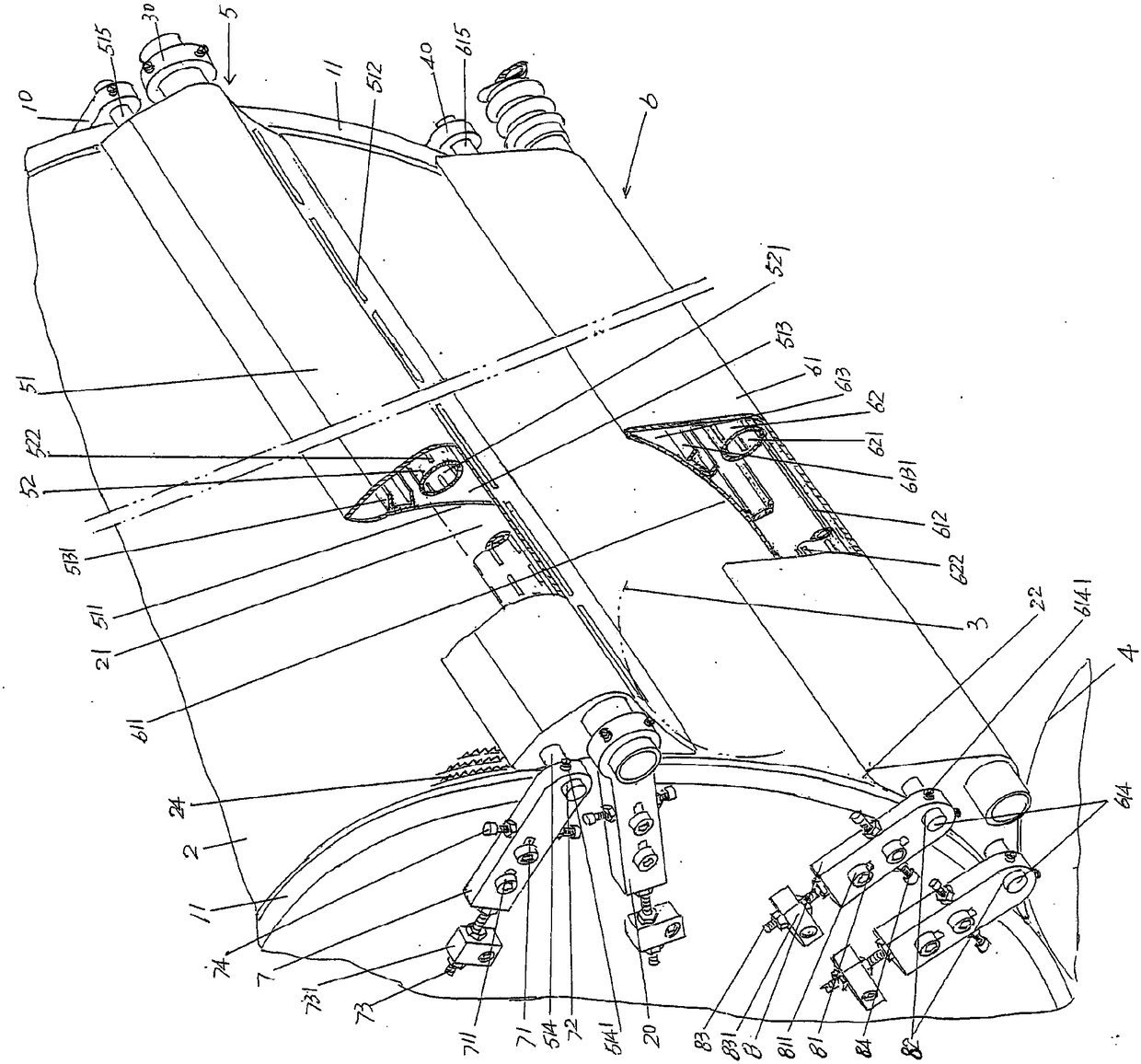
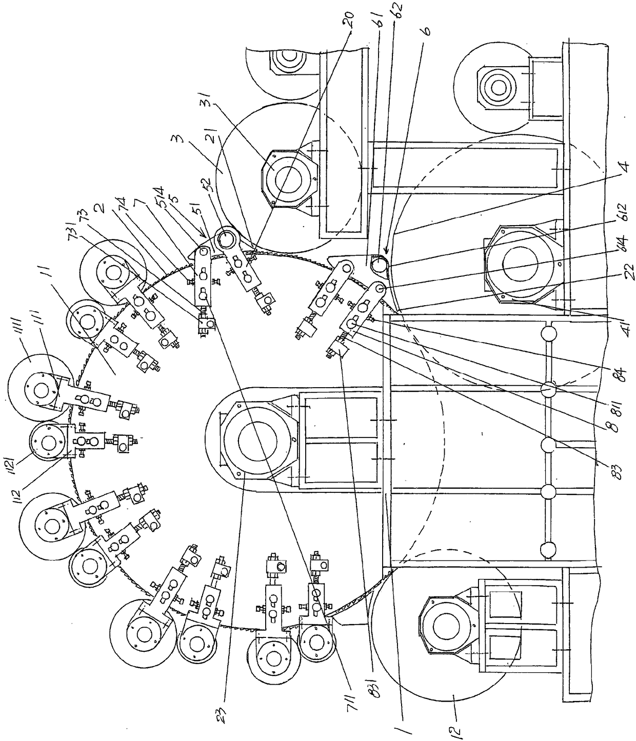
[0022] In the following descriptions, all concepts involving directionality or orientation of up, down, left, right, front and rear are aimed at figure 1 As far as the position state shown is concerned, it cannot be understood as a special limitation on the technical solution provided by the present invention.

[0023] See figure 1 , showing the passing of the main carding roll bearing housing 23 ( figure 2 Shown) the main carding roll 2, which is rotatably supported on the frame 1, corresponds to the right side of the main carding roll 2 and passes...


PUM


Abstract

The invention belongs to the technical field of non-woven machines and relates to a high-speed carding machine. The high-speed carding machine comprises a main carding roll, an upper cotton discharge roll and a lower cotton discharge roll, a pair of main carding roll wallboards is fixed on a rack and at the positions respectively corresponding to the front end face and the rear end face of the main carding roll, a space between the main carding roll and the upper cotton discharge roll forms an upper triangle, and a space between the main carding roll and the lower cotton discharge roll forms a lower triangle. The high-speed carding machine is characterized in that an upper triangle airflow dissolving mechanism is arranged at the position corresponding to the upper triangle and used for dissolving airflow of the upper triangle and enabling negative pressure to be formed in the upper triangle; a lower triangle airflow dissolving mechanism is arranged at the position corresponding to the lower triangle and used for dissolving airflow of the lower triangle and enabling negative pressure to be formed in the lower triangle; the upper triangle airflow dissolving mechanism and the lower triangle airflow dissolving mechanism are respectively supported between the main carding roll wallboards. Carding rings are reduced, CV value is lowered, and lapping quality of follow-up stations is improved.

Description

technical field [0001] The invention belongs to the technical field of non-woven machinery, and in particular relates to a high-speed carding machine. Background technique [0002] The aforementioned carding machine is also called a carding machine, which is an important part of a complete set of non-woven product production equipment. As known in the industry, a complete set of non-woven products such as non-woven fabrics or non-woven felt production equipment mainly includes an opener, a carding machine, a laminating machine and a needle punching machine (or hydroentanglement machine). The non-woven fiber after the machine is opened is carded and fed to the web-laying machine by the cotton outlet roller, and then sent to the needle-punching machine for needle punching or the spunlace machine to form a non-woven product. [0003] The technical information about the carding machine can be seen in the published Chinese patent literature, such as the authorized announcement n...

Claims


Application Information

Patent Timeline
Patent Type & Authority Patents(China)
IPC IPC(8): D01G15/26D01G15/74
CPCD01G15/26D01G15/74
Inventor 范立元
Owner JIANGSU YINGYANG NONWOVEN MASCH CO LTD
Why Eureka
Eureka Blog
Learn More