
Installation structure of one-way clutch

一种单向离合器、构造的技术,应用在单向离合器、离合器、联轴器等方向,能够解决动作不良等问题

Active Publication Date: 2016-12-14
TOYOTA JIDOSHA KK
View PDF12 Cites 0 Cited by
  • Summary
  • Abstract
  • Description
  • Claims
  • Application Information

AI Technical Summary

Problems solved by technology

Even in such a structure, the members constituting the OWC are fastened by rivets, and if the rivets are badly fastened, malfunctions may occur due to the rivets coming off.

Method used


Image

  • Installation structure of one-way clutch
  • Installation structure of one-way clutch
  • Installation structure of one-way clutch

Examples


Embodiment Construction

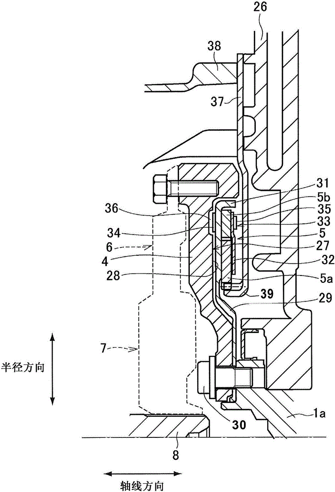
[0029] Image 6 It is a schematic diagram showing an example of a power train equipped with a one-way clutch according to an embodiment of the present invention. The power train shown here includes an engine (ENG) 1 and a first electric motor (MG1) 2 and a second electric motor (MG2) 3 as driving power sources. A flywheel 4 is attached to the output shaft (crankshaft) 1a of the engine 1. A one-way clutch (hereinafter referred to as OWC) 5 that prevents the output shaft 1a from rotating in the negative direction (rotation in the opposite direction to the rotating direction of the engine 1) of the output shaft 1a together with the flywheel 4 is provided. The structure of OWC5 is described later.

[0030] A damper mechanism 7 is connected to the flywheel 4 via a torque limiter 6, and an input shaft 8 is connected to the damper mechanism 7. The torque limiter 6 is a well-known structure in which a plate on the driving side and a plate on the driven side are brought into frictional...


PUM


Abstract

An installation structure of a one-way clutch can inhibit or avoid weak rivet of a rivet assemblies the one-way clutch and weak movement due to disconnection of a rivet part or a heat part. The installation structure (5) of the one-way clutch includes a maintenance board (29) between rotary bodies (5a, 5b) and a flywheel (4). The maintenance board (29) is used for conencting a second rotary body (5b) and is connected to the flywheel (4). A fastening board (32) which maintains the rotary bodies in an assemblied status is disposed on side surface, which is opposite to the flywheel, along the rotary bodies (5a, 5b). The fastening board (32), the second rotary body (5b), the maintenance board (29) are conencted through a rivet (33). Distance (C1) between one end of the rivit and the flywheel (4) is smaller than the thickness (T1) of the fastening board (32).

Description

Technical field [0001] The present invention relates to a one-way clutch mounting structure configured to transmit torque in a first rotation direction and not transmit torque in a second rotation direction opposite to the first rotation direction. Background technique [0002] Patent Document 1 describes an example of a one-way clutch (hereinafter referred to as OWC) mounted on the output shaft of the engine. The OWC is a structure in which a wedge is arranged between an outer ring and an inner ring arranged on a concentric circle. The OWC is fitted so that the outer ring is integrated with the outer periphery of the disc-shaped member, and the inner ring supports the OWC The outer ring of the bearing is integrated. That is, in the OWC of Patent Document 1, the movement of the outer ring and the inner ring in the axial direction is restricted by the disc-shaped member and the bearing, and the assembled state is maintained. [0003] On the other hand, the OWC described in Patent ...

Claims


Application Information

Patent Timeline
Patent Type & Authority Applications(China)
IPC IPC(8): F16D41/00
CPCF16D41/00B60K6/365B60K6/383B60K6/405B60K6/445F16D41/12Y02T10/62Y10S903/91Y10S903/913Y10S903/96B60K6/30B60Y2200/92B60Y2400/427F16D2300/12F16D2300/22
Inventor 远藤隆人信安清太郎铃木阳介加藤晃一岩濑雄二
Owner TOYOTA JIDOSHA KK
Features
  • Generate Ideas
  • Intellectual Property
  • Life Sciences
  • Materials
  • Tech Scout
  • Unparalleled Data Quality
  • Higher Quality Content
  • 60% Fewer Hallucinations
Learn More