Supercharge Your Innovation With Domain-Expert AI Agents!

Cupola device for rock wool production and distribution method thereof

A technology for cupola and rock wool, which is applied to the field of cupola devices for rock wool production, can solve the problems of uneven coke material mixing, low production line output, and high coke unit consumption, and achieve improved melting temperature, melting rate, and coke-material ratio. The effect of low, high melt capacity

Active Publication Date: 2016-12-14
TAISHI ROCK WOOL
View PDF7 Cites 0 Cited by
  • Summary
  • Abstract
  • Description
  • Claims
  • Application Information

AI Technical Summary

Problems solved by technology

[0002] At present, with the development of the national economy and the implementation of the national energy-saving policy, the demand for rock and mineral wool products for building and industrial thermal insulation is increasing. However, the existing cupolas for the production of rock and mineral wool are rated at The melting amount of raw materials does not exceed 5 tons / hour, and the designed production capacity of a rock and mineral wool production line is only 28,000 tons / year
The existing cupola furnace body is cylindrical and adopts the splicing method of straight pipes. The capacity is limited, which limits the production capacity. If the volume of the cylinder is simply enlarged, the coke material will be mixed unevenly, and it cannot be guaranteed that the raw materials in the furnace body can be melted , and its low melting capacity is the main reason for the low output of the production line. The coke of the traditional process is mixed with the raw materials and put into the furnace together. The coke material is not mixed uniformly, the unit consumption of coke is high, the melting temperature is low and the melting rate is low.

Method used


Image

  • Cupola device for rock wool production and distribution method thereof
  • Cupola device for rock wool production and distribution method thereof

Examples


Embodiment Construction

[0024] In order to have a clearer understanding of the technical features, purposes, effects and embodiments of the present invention, specific implementations of the present invention will now be described in conjunction with the accompanying drawings.

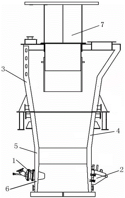
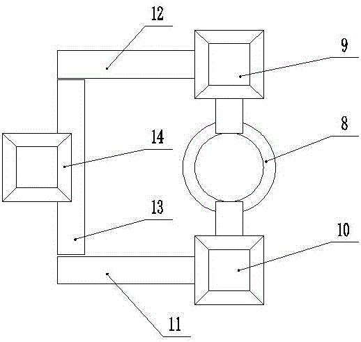
[0025] Such as figure 1 and figure 2 As shown, a cupola device for rock wool production includes a cupola and a material distribution device. The cupola is located below the material distribution device. The material distribution device includes a hoist 14, a transition belt 13, a belt I12, a belt II11, a hopper II10, and a hopper Ⅰ9, distributor 8, and hoist 14 are arranged in the middle above the transition belt 13. The two ends of the transition belt 13 are respectively close to the ends of belt I12 and belt II11. The other end of belt I12 is connected to the hopper I9 and belt II11 for storing coke. The other end is connected to the hopper II10 for storing raw materials, both the hopper II10 and the hopper I9 are connec...


PUM


Abstract

The invention discloses a cupola device for rock wool production. The cupola device comprises a cupola and a distribution device; the distribution device includes a lifter, a transition belt, a belt I, a belt II, a hopper II, a hopper I and a distributor; the lifter is arranged above the transition belt; two ends of the transition belt are respectively near the end of the belt I and the end of the belt II; the other end of the belt I is connected with the hopper I; the other end of the belt II is connected with a hopper II; the hopper II and the hopper I are both connected with the distributor; the cupola includes upper and lower furnace bodies; a cupola throat pipe is arranged at the upper part of the upper furnace body; the upper end of the cupola throat pipe is connected with the distributor; the lower furnace body is divided into a lower furnace body upper section, a lower furnace body middle section and a lower furnace body lower section from top to bottom; an intake device and a siphon port are arranged at the lower furnace body lower section; a cooling device I is arranged on the outer wall of the upper furnace body; a cooling device II is arranged on the outer wall of the lower furnace body; the upper furnace body, the lower furnace body upper section and the lower furnace body lower section are all cones; and the lower furnace body middle section is a cylinder.

Description

technical field [0001] The invention relates to the technical field of rock wool production equipment, in particular to a cupola device for rock wool production and a material distribution method thereof. Background technique [0002] At present, with the development of the national economy and the implementation of the national energy-saving policy, the demand for rock and mineral wool products for building and industrial thermal insulation is increasing. However, the existing cupolas for the production of rock and mineral wool are rated at The melting amount of raw materials does not exceed 5 tons per hour, and the designed production capacity of a rock and mineral wool production line is only 28,000 tons per year. The existing cupola furnace body is cylindrical and adopts the splicing method of straight pipes. The capacity is limited, which limits the production capacity. If the volume of the cylinder is simply enlarged, the coke material will be mixed unevenly, and it ca...

Claims


Application Information

Patent Timeline
Patent Type & Authority Applications(China)
IPC IPC(8): F27B1/02F27B1/20F27B1/24
CPCF27B1/02F27B1/20F27B1/24
Inventor 彭文龙曹国良吕杨
Owner TAISHI ROCK WOOL
Features
  • R&D
  • Intellectual Property
  • Life Sciences
  • Materials
  • Tech Scout
  • Unparalleled Data Quality
  • Higher Quality Content
  • 60% Fewer Hallucinations
Learn More