A kind of transient electromagnetic wire frame for railway tunnel and using method

A transient electromagnetic and tunneling technology, which is applied in the direction of re-radiation, electric/magnetic exploration, and acoustic re-radiation, can solve the problems of data processing influence, inconvenient carrying of brackets, and inaccurate results, so as to ensure measurement accuracy , Easy to assemble and operate, simple device structure

Active Publication Date: 2019-07-12
SHANDONG UNIV
View PDF7 Cites 0 Cited by
  • Summary
  • Abstract
  • Description
  • Claims
  • Application Information

AI Technical Summary

Problems solved by technology

[0003] At present, the commonly used method of fixing the transmitting coil in the tunnel is mainly fixed by an external bracket, which is generally inconvenient to carry, time-consuming and laborious to assemble, and there is no device for fixing the receiving probe, which affects the construction efficiency
In the transient electromagnetic detection of tunnels, there are often certain requirements for the angle between the wire frame and the tunnel surface. In the actual application process, operators often place them based on subjective analysis, without corresponding instruments to restrict them, which will affect the detection data. The accuracy of the data will affect the later data processing
The existing measuring device can only be placed in one position for measurement. When it is necessary to measure in other positions, the measurement device needs to be moved as a whole to complete the measurement. It is inconvenient to adjust, and the final result may be caused by personnel adjustment errors during the adjustment process. Not accurate enough

Method used


Image

  • A kind of transient electromagnetic wire frame for railway tunnel and using method
  • A kind of transient electromagnetic wire frame for railway tunnel and using method
  • A kind of transient electromagnetic wire frame for railway tunnel and using method

Examples


Embodiment Construction

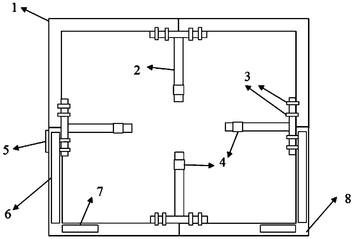
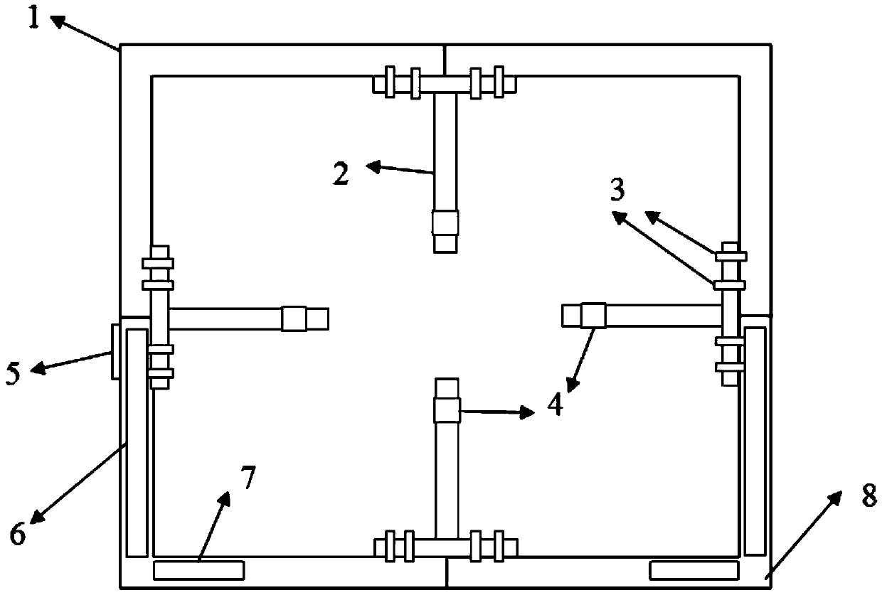
[0036] The present invention will be further described below in conjunction with the accompanying drawings and embodiments.

[0037] Such as Figure 1-Figure 2 As shown, the transient electromagnetic wire frame used for the railway tunnel includes a positioning frame, and the positioning frame is composed of two upper positioning frame assemblies 1 and two lower positioning frame assemblies 8, the upper positioning frame assembly 1 and the upper positioning frame assembly 1 between the lower positioning frame assembly 8 and the lower positioning frame assembly 8, and between the upper positioning frame assembly 1 and the lower positioning frame assembly 8 are all fixedly connected by the positioning frame connector 2; the positioning frame connector 2 is provided with a card slot 4 , whose function is to fix the receiving coil and the transmitting coil. The outer part of the lower positioning frame assembly 8 is provided with a slope gauge 5, and its function is to measure th...


PUM


Abstract

The invention discloses a transient electromagnetic wire frame used for a railway tunnel and a use method thereof. The transient electromagnetic wire frame comprises a positioning frame which is formed by multiple positioning frame components which are fixedly connected through positioning frame connectors. The positioning frame connectors are provided with clamp slots for fixing receiving coils and transmitting coils. The side part of the positioning frame is connected with an adjusting support. An angle measurement device is fixed on the positioning frame. The bottom part of the positioning frame and the adjusting support is matched with a slide device. The positioning frame slides along the slide device to complete electromagnetic detection. The whole device is simple in structure, low in cost and easy to assemble and operate; the inclined angle between the positioning frame and a tunnel face and a base plate can be accurately measured by a tilt gauge and the angle measurement device so that the influence of onsite subjective judgment on detection can be avoided; and the receiving coils can be fixed on the positioning frame so that error of detection caused by handholding the receiving coils can be avoided.

Description

technical field [0001] The invention relates to a transient electromagnetic wire frame used in a railway tunnel and a using method. Background technique [0002] The transient electromagnetic transmitting coil is used to generate the primary field in the detection of transient electromagnetic method. In the tunnel transient electromagnetic method exploration, the fixation of the transmitting coil and the change of the placement angle of the wire frame have always been the difficulties that restrict the detection efficiency. [0003] At present, the commonly used method of fixing the transmitting coil in the tunnel is mainly fixed by an external bracket, which is generally inconvenient to carry, time-consuming and laborious to assemble, and there is no device for fixing the receiving probe, which affects the construction efficiency. In the transient electromagnetic detection of tunnels, there are often certain requirements for the angle between the wire frame and the tunnel ...

Claims


Application Information

Patent Timeline
Patent Type & Authority Patents(China)
IPC IPC(8): G01V3/10
CPCG01V3/10
Inventor 李术才卜林石少帅徐飞刘洪亮贺鹏胡杰张云鹏
Owner SHANDONG UNIV
Why Eureka
Try Eureka