Power battery tab adhesive encapsulation device and adhesive encapsulation method thereof

A technology of power battery and rubber wrapping device, which is applied in the direction of battery pack parts, circuits, electrical components, etc., can solve the problems of unsatisfactory quality and appearance of the finished battery, insufficient flatness of the glue wrap, and easy-to-open glue of the tape, so as to avoid battery extremes. The effects of ear short circuit, flexible device and firm tape

Active Publication Date: 2016-12-14
江苏维利科自动化技术有限公司
View PDF4 Cites 3 Cited by
  • Summary
  • Abstract
  • Description
  • Claims
  • Application Information

AI Technical Summary

Problems solved by technology

However, there are still some deficiencies in the existing battery tab automatic rubber-covering molding device, which hinders the development of the industry.
At present, there are also some patents on the tab rubber, such as a tab tab device (country: China, publication number: CN103474612A, publication date: 2013-12-25), which discloses the use of a workbench to drive the first push block, The second push block rises, so that the adhesive paper attached to the tab changes from a horizontal state to a vertical state. When the bottom of the first push block and the bottom of the second push block move to the same height as the tab, the first push block The block and the second push block press the tape respectively and move towards the middle of the workbench, so that the tape is covered on the tab. This device improves the production efficiency, but because the tape on both sides is only covered on the upper surface of the tab respectively, The tape is easy to unglue, and at the same time, the method of encapsulation is not smooth enough, the quality and appearance of the finished battery produced are not ideal, and the device is more complicated

Method used


Image

  • Power battery tab adhesive encapsulation device and adhesive encapsulation method thereof
  • Power battery tab adhesive encapsulation device and adhesive encapsulation method thereof
  • Power battery tab adhesive encapsulation device and adhesive encapsulation method thereof

Examples


Embodiment Construction

[0027] Below in conjunction with accompanying drawing and specific embodiment, further illustrate the present invention, should be understood that these embodiments are only for illustrating the present invention and are not intended to limit the scope of the present invention, after having read the present invention, those skilled in the art will understand various aspects of the present invention Modifications in equivalent forms all fall within the scope defined by the appended claims of this application.

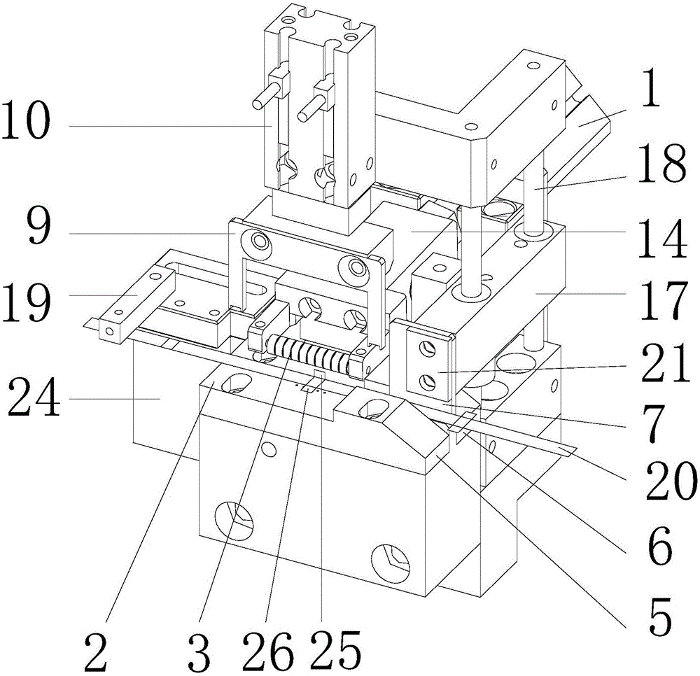
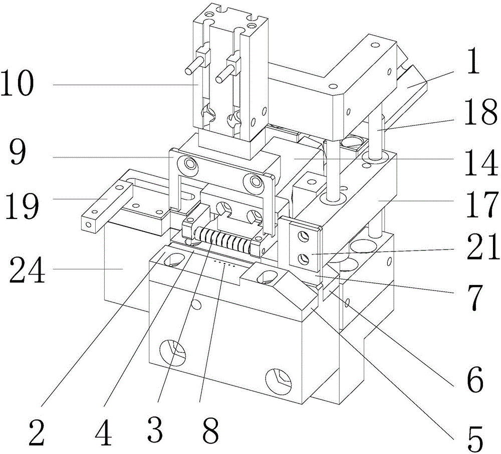
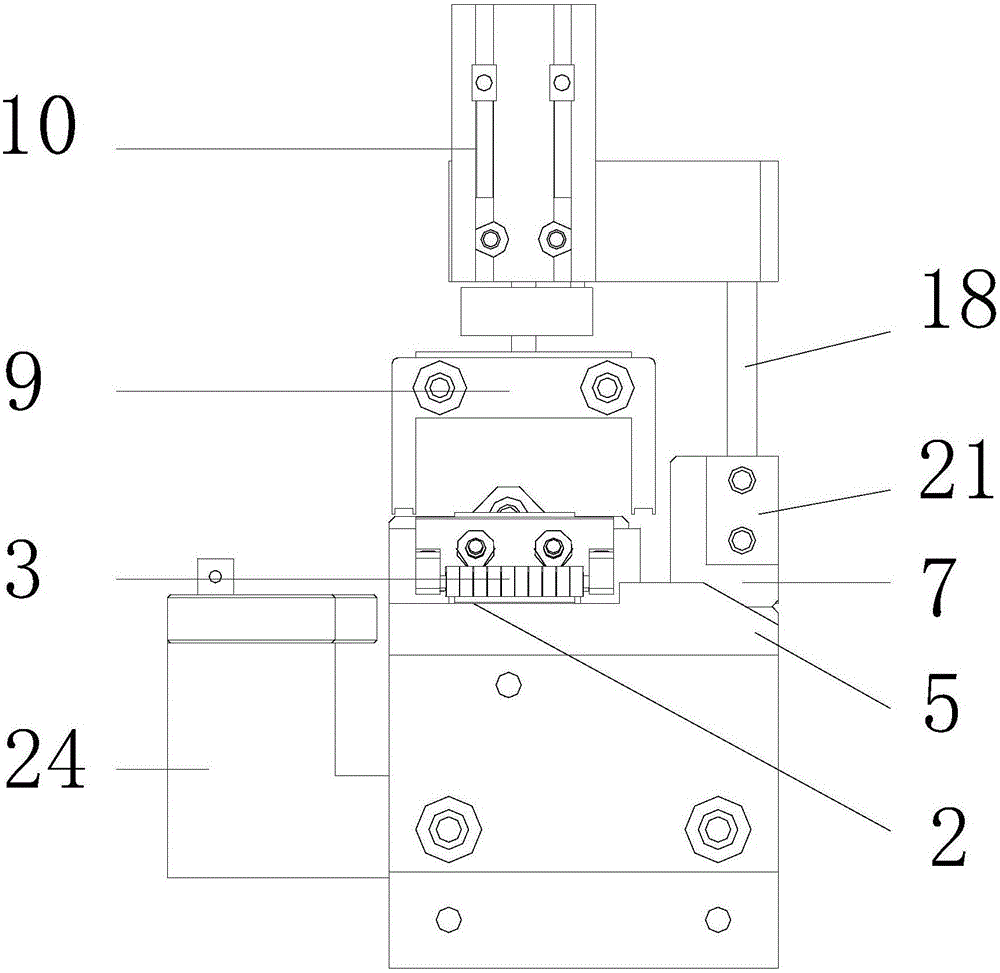
[0028] A power battery lug wrapping device, including a wrapping driver 1, a guide table 2, a pressure head 3, a channel 4, a front limit block 5, a rear limit block 6, a baffle plate 7, an air blowing hole 8, a positioning Fork 9, press cylinder 10, slide rail 11, slide block 12, briquetting base plate 13, briquetting 14, elastic member 15, top block 16, baffle plate adjustment block 17, guide rod 18, pressing plate 19, fixed plate 21, Pressure head support 22, cylinder...


PUM


Abstract

The invention discloses a power battery tab adhesive encapsulation device and an adhesive encapsulation method thereof. The device comprises an adhesive encapsulation driver, a guide table and a pressing head for pressing adhesive tapes. The adhesive encapsulation driver drives the pressing head to carry out reciprocating motion on the guide table. The guide table is equipped with a channel for a tab to pass. The direction of the channel is vertical to the motion direction of the pressing head. A front side limiting block and a rear side limiting block are arranged at the inlet sides of the channel of the guide table. The front side limiting block and the rear side limiting block are located at two sides of the width of the channel. The front side limiting block and the rear side limiting block are slops at the inlet end of the channel. The bottom ends of the slopes are lower than the channel. A baffle plate is arranged above the channel. The baffle plate is located between the front side limiting block and the rear side limiting block and is adjacent to the rear side limiting block. An air blowing hole is arranged at the center of the guide table. The invention also discloses an adhesive encapsulation method employing the device. The device and the method have the advantages that laminated adhesive encapsulation is carried out on the tab, the adhesive tapes are firmer, an adhesive failure is not liable to generate when electrolyte is injected into a battery, the battery tab short circuit resulting from adhesive failure can be avoided, and the production loss is reduced.

Description

technical field [0001] The invention relates to an automatic production device for a power battery, in particular to a battery lug wrapping device and a wrapping method thereof. Background technique [0002] In order to prevent the tabs of the battery from short-circuiting, before the tabs are welded, the exposed parts of the tabs are covered with glue in advance. However, there are still some deficiencies in the existing battery lug automatic overmolding device, which hinders the development of the industry. At present, there are also some patents about the tab rubber, such as a tab rubber coating device (country: China, publication number: CN103474612A, publication date: 2013-12-25), which discloses the use of a workbench to drive the first push block, The second push block rises, so that the adhesive paper attached to the tab changes from a horizontal state to a vertical state. When the bottom of the first push block and the bottom of the second push block move to the sa...

Claims


Application Information

Patent Timeline
Patent Type & Authority Applications(China)
IPC IPC(8): H01M2/26H01M50/531
CPCH01M50/531Y02E60/10
Inventor 吉跃华袁伟宏杜隆
Owner 江苏维利科自动化技术有限公司
Why Eureka
Try Eureka