M-sequence pseudo random interleaving identification method in non-cooperated condition

A recognition method, m-sequence technology, applied in the field of communication signal recognition, can solve problems such as difficulty in recognition of interleaved permutation relations

Active Publication Date: 2016-12-14
ELECTRONICS ENG COLLEGE PLA
View PDF4 Cites 8 Cited by
  • Summary
  • Abstract
  • Description
  • Claims
  • Application Information

AI Technical Summary

Problems solved by technology

[0003] Pseudo-random interleaving is very difficult to identify the interleaving permutation relationship due to the relatively complex symbol mapping relationship in the interleaving proce

Method used


Image

  • M-sequence pseudo random interleaving identification method in non-cooperated condition
  • M-sequence pseudo random interleaving identification method in non-cooperated condition
  • M-sequence pseudo random interleaving identification method in non-cooperated condition

Examples


Embodiment 1

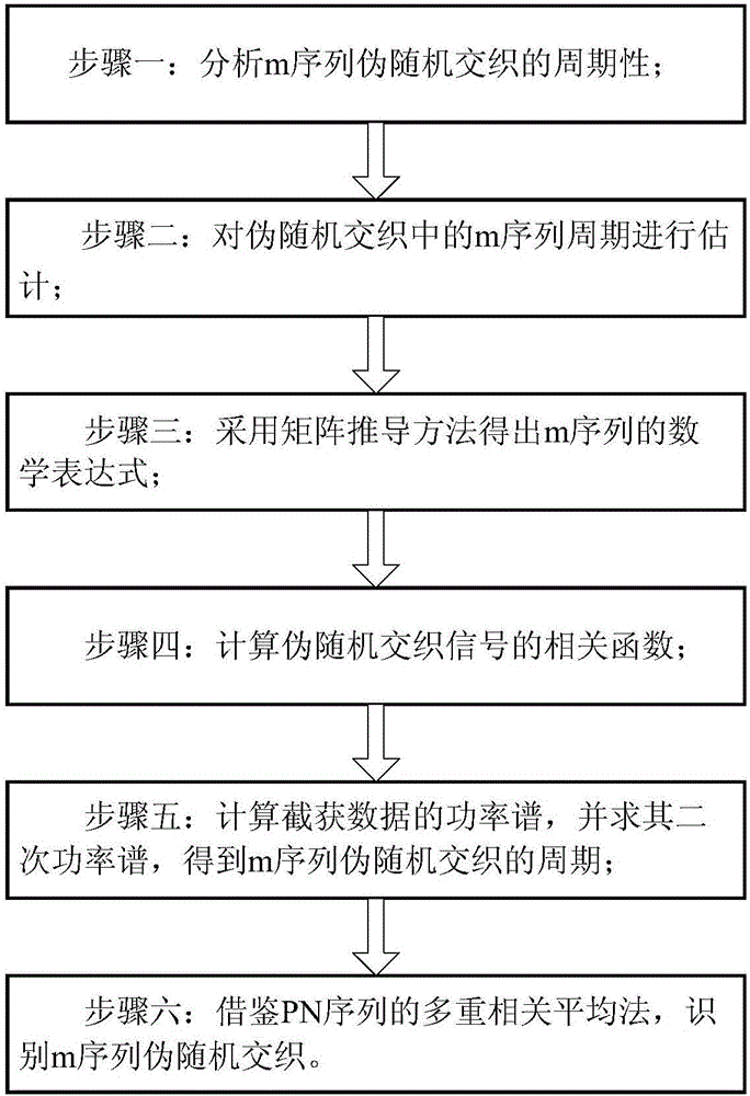
[0089] Embodiment 1: see figure 1 , an m-sequence pseudo-random interleaving identification method under a non-cooperative condition, which includes the following steps:

[0090] Step 1: analyzing the periodicity of m-sequence pseudo-random interleaving;

[0091] The structure of the m-sequence generator is a high-speed linear feedback shift register generator. By analyzing the structure of the generator, it can be obtained that the feedback connection is determined by the polynomial (1):

[0092] g(D)=1+g 1 D+g 2 D. 2 +…+g r D. r (1)

[0093] Its output is:

[0094]

[0095] where D is the unit delay variable, its power represents the delay, g i Selected from the set {0,1}, a(D) represents the initial state of the shift register;

[0096] If g(D) is a primitive polynomial, then the sequence generated by the high-speed linear feedback shift register has a maximum length, derived as follows:

[0097] Each of the possibilities loaded into the high-speed linear feed...


PUM


Abstract

The invention discloses a m-sequence pseudo random interleaving identification method in a non-cooperated condition. The method comprises the steps of analyzing periodicity in m-sequence pseudo random interleaving, estimating a m-sequence period in pseudo random interleaving, obtaining a mathematical expression of a m-sequence e(t) according to a matrix derivation method, calculating a related function of a pseudo random interleaving signal f(t), calculating a related function of the pseudo random interleaving signal f(t), calculating the power spectrum of intercepted data, calculating a secondary power spectrum, deriving the period in m-sequence pseudo random interleaving, identifying m-sequence pseudo random interleaving in reference to a PN-sequence multi-scale correlation averaging method. The m-sequence pseudo random interleaving identification method can effectively settle a problem of identifying a pseudo random interleaving sequence in the non-cooperated condition. The m-sequence pseudo random interleaving identification method has advantages of simple process, high identification accuracy, high convenience in application, etc. Furthermore communication signal identification capability can be greatly improved.

Description

technical field [0001] The invention belongs to the field of communication signal identification, in particular to an identification method for m-sequence pseudo-random interleaving. Background technique [0002] The purpose of digital information transmission systems is to send, transmit and receive information safely and efficiently. Both parties in the communication are usually partners. For the partner, when the receiver receives the transmitted signal, it needs to demodulate the signal according to the modulation style used by the partner, and then implement channel decoding, source decoding, etc. These steps The transferred information cannot be retrieved until complete. The modulation scheme, channel coding parameters (including interleaving parameters, error correction coding parameters, and scrambling parameters), source coding parameters, and passwords used in signal transmission are agreed in advance by the communication parties or notified to the receiver throug...

Claims


Application Information

Patent Timeline
IPC IPC(8): H04L1/00
CPCH04L1/0045H04L1/0071
Inventor 张玉唐波杨晓静张进廖斌张岱彭贻云张浩徐舟马宇飞金儒男
Owner ELECTRONICS ENG COLLEGE PLA
Why Eureka
Try Eureka