
PWM isolation dimming circuit and LED dimming driving power source

A technology of dimming circuit and PWM signal, applied in the field of dimming, can solve the problems of large volume and high cost of linear distortion of isolated dimming circuit

Active Publication Date: 2016-12-14
TCL VERY LIGHTING TECH HUIZHOU CO LTD +1
View PDF2 Cites 16 Cited by
  • Summary
  • Abstract
  • Description
  • Claims
  • Application Information

AI Technical Summary

Problems solved by technology

[0005] Based on this, it is necessary to provide a PWM isolated dimming circuit and LED dimming drive power supply for the shortcomings of the existing isolated dimming circuit, such as severe linear distortion, large size, and high cost.

Method used


Image

  • PWM isolation dimming circuit and LED dimming driving power source
  • PWM isolation dimming circuit and LED dimming driving power source
  • PWM isolation dimming circuit and LED dimming driving power source

Examples


Embodiment Construction

[0040] In order to make the above objects, features and advantages of the present invention more comprehensible, specific implementations of the present invention will be described in detail below in conjunction with the accompanying drawings. In the following description, numerous specific details are set forth in order to provide a thorough understanding of the present invention. However, the present invention can be implemented in many other ways different from those described here, and those skilled in the art can make similar improvements without departing from the connotation of the present invention, so the present invention is not limited by the specific embodiments disclosed below.

[0041] In addition, the terms "first" and "second" are used for descriptive purposes only, and cannot be interpreted as indicating or implying relative importance or implicitly specifying the quantity of indicated technical features. Thus, the features defined as "first" and "second" may ...


PUM


Abstract

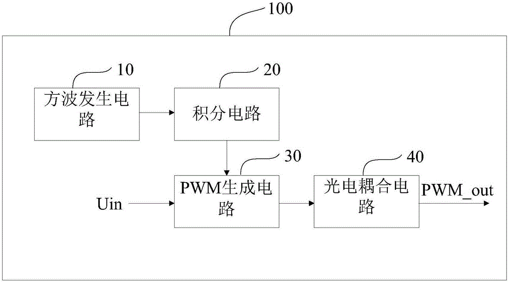
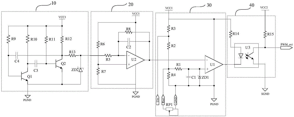
The present invention relates to a PWM isolation dimming circuit and an LED dimming driving power source, wherein the PWM isolation dimming circuit comprises: a square-wave generator circuit, used to generate a square-wave signal by oscillation; an integrating circuit, wherein an input end thereof is connected to an output end of the square-wave generator circuit, and the integrating circuit is used to perform an integral operation on the square-wave signal, to generate a triangle-wave signal; a PWM generator circuit, wherein an input end thereof is connected to an input end of a dimming signal and an output end of the integrating circuit, and the PWM generator circuit is used to compare the dimming signal with the triangle-wave signal, generate a PWM signal according to a comparison result, adjust a duty ratio of the PWM signal and output an adjusted PWM signal; and a photocoupling circuit, wherein an input end thereof is connected to an output end of the PWM generator circuit, and an output end thereof is connected to a control end of an LED driving power source, to control an output current of the driving power source. The foregoing PWM isolation dimming circuit and LED dimming driving power source have advantages of being good in degree of linearity, small in circuit volume, and low in costs because a high-frequency transformer is unnecessary.

Description

technical field [0001] The invention relates to the technical field of dimming, in particular to a PWM isolated dimming circuit and an LED dimming drive power supply using the PWM isolated dimming circuit. Background technique [0002] With the rapid development of electronic technology, LED lighting products are gradually becoming intelligent. In order to achieve power saving, scene lighting control and other purposes, LED lighting with dimming function is more and more widely used. [0003] At present, a widely used LED dimming technology is PWM (Pulse Width Modulation, pulse width modulation) technology, which uses the human eye's insensitivity to high-frequency flicker and the induction and accumulation characteristics of brightness to control the on and off of the LED light source through the PWM signal. , adjust the duty cycle of the PWM signal to adjust the lighting time of the LED light source. When the duty cycle of the PWM signal is larger, the longer the LED light...

Claims


Application Information

Patent Timeline
Patent Type & Authority Applications(China)
IPC IPC(8): H05B33/08H05B44/00
CPCH05B45/00Y02B20/30
Inventor 钟少强
Owner TCL VERY LIGHTING TECH HUIZHOU CO LTD
Learn More