Control method of driver fatigue monitoring system

A driver fatigue monitoring system technology, applied in the field of driver fatigue monitoring system control, can solve the problems of driver discomfort, difficult driver classification, easy to be affected by the driver and the environment, and achieve accurate monitoring Effect

Inactive Publication Date: 2016-12-21
合肥飞鸟信息技术有限公司
View PDF8 Cites 15 Cited by
  • Summary
  • Abstract
  • Description
  • Claims
  • Application Information

AI Technical Summary

Problems solved by technology

[0003] There are many deficiencies in these existing monitoring systems: First, the method for extracting the characteristics of driver fatigue is still under study at home and abroad, and there are deficiencies in extracting fatigue features from the collected signals through time domain or frequency domain methods. At present, there is no effective feature recognition method for the correlation between human physiological and medical signals such as breathing, pulse and heart rate combined with the theory of traditional Chinese medicine and driver fatigue, so it is difficult to accurately classify the driver's fatigue; other Second, since most of the fatigue monitoring sensors are contact, the signal acquisition during driving is easily affected by the driver and the environment, which is likely to cause discomfort to the driver and affect his driving operation, so it is difficult to accurately identify driver fatigue , and the method of monitoring through non-contact instruments such as on-board cameras and radars is often more dependent on the external environment, and the monitoring accuracy is likely to be low due to environmental changes; The relationship between the fatigue degree and the monitoring indicators is well quantified, and the classification of fatigue is not accurate enough; Fourth, due to the individual differences of drivers and the influence of the environment, the monitoring method of a single monitoring indicator has limitations

Method used


Image

  • Control method of driver fatigue monitoring system
  • Control method of driver fatigue monitoring system

Examples


Embodiment Construction

[0009] Combine below Figure 1 to Figure 2 , the present invention is described in further detail.

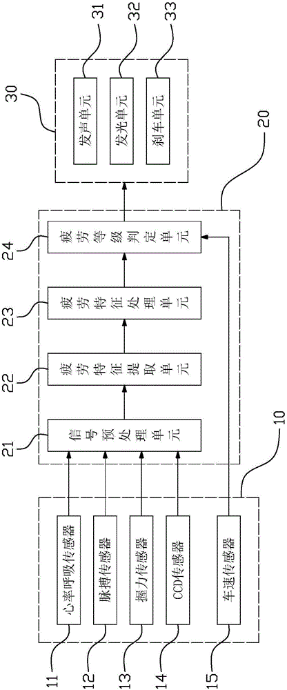
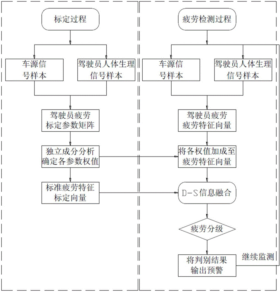
[0010] refer to figure 2 , a control method of a driver fatigue monitoring system, comprising the following steps: (A) signal acquisition module 10 collects heart rate, respiration, pulse, steering wheel grip and vehicle line change frequency information of the driver in an awake state and outputs them to the control module 20 (B) control module 20 obtains each parameter weight and standard fatigue characteristic calibration vector after the information of step A output is processed; (C) signal collection module 10 collects heart rate, breathing, pulse, steering wheel grip and The vehicle lane change frequency information is output to the control module 20; (D) the control module 20 preprocesses the information output in step C to obtain the driver fatigue feature vector, and calculates the driver fatigue according to each parameter weight and the standard fatigue feature cal...


PUM


Abstract

The invention particularly relates to a control method of a driver fatigue monitoring system. The method includes steps: (A) a signal acquisition module acquires data when a driver is sober and outputs to a control module; (B) the control module calibrates vectors for standard fatigue characteristics and parameter weights obtained after processing; (C) a signal acquisition module acquires data when the driver drives a vehicle and outputs to the control module; (D) the control module performs preprocessing to obtain fatigue characteristic vectors of the driver and processes to obtain fatigue levels; (E) the control module drives an alarm module to act according to the fatigue levels; (F) repeating the step C, D and E to monitor continuously. By monitoring of heart rate, respiration, pulse, steering wheel holding force and vehicle line changing efficiency, the fatigue state of the driver can be detected more reliably and accurately; by adoption of the data acquired in a sober state of the driver as a reference, adaptability of the method is improved.

Description

technical field [0001] The invention relates to the technical field of driving safety, in particular to a control method of a driver fatigue monitoring system. Background technique [0002] About 1.2 million people die in traffic accidents every year in the world. Studies have shown that fatigue driving is one of the important reasons for road traffic accidents. In order to avoid the harm caused by fatigue driving, many people have developed driver fatigue monitoring systems. Said that driver fatigue monitoring methods are generally divided into subjective fatigue monitoring and objective fatigue monitoring. At present, the detection methods based on driving fatigue mainly focus on the monitoring and early warning of objective fatigue. The objective fatigue monitoring mainly uses various detection instruments to monitor the specificity of the driver's physical index or driving behavior state in real time, objectively evaluate and give prompts and early warnings. method. ...

Claims


Application Information

Patent Timeline
Patent Type & Authority Applications(China)
IPC IPC(8): A61B5/0205A61B5/22A61B5/18A61B5/00B60Q9/00B60T7/12G08B21/06
CPCA61B5/0205A61B5/02A61B5/024A61B5/08A61B5/168A61B5/18A61B5/225A61B5/681A61B5/6831A61B5/6893A61B5/7203A61B5/7235A61B5/7264A61B5/7275A61B5/7405A61B5/742A61B5/746A61B2503/22B60Q9/00B60T7/12G08B21/06
Inventor 郑守国张双双王勇张邢龙白磊李伯丽
Owner 合肥飞鸟信息技术有限公司
Why Eureka
Try Eureka