Eureka AIR delivers breakthrough ideas for toughest innovation challenges, trusted by R&D personnel around the world.

A stepped stent suitable for tapered vessels

A step-shaped, vasoconstricting technology, applied in the field of medical devices, can solve the problems of insufficient radial stiffness of balloon-expandable stents, radial retraction of stents, unstable deformation, etc., so as to improve the hemodynamic environment and improve diameter. Effects introduced to stiffness, reduction

Inactive Publication Date: 2018-01-16
JIANGSU UNIV
View PDF9 Cites 0 Cited by
  • Summary
  • Abstract
  • Description
  • Claims
  • Application Information

AI Technical Summary

Problems solved by technology

Insufficient radial stiffness of the balloon-expandable stent will not only lead to radial retraction of the stent, but may also cause collapse or instability deformation, resulting in serious medical consequences

Method used


Image

  • A stepped stent suitable for tapered vessels
  • A stepped stent suitable for tapered vessels
  • A stepped stent suitable for tapered vessels

Examples


Embodiment example 1

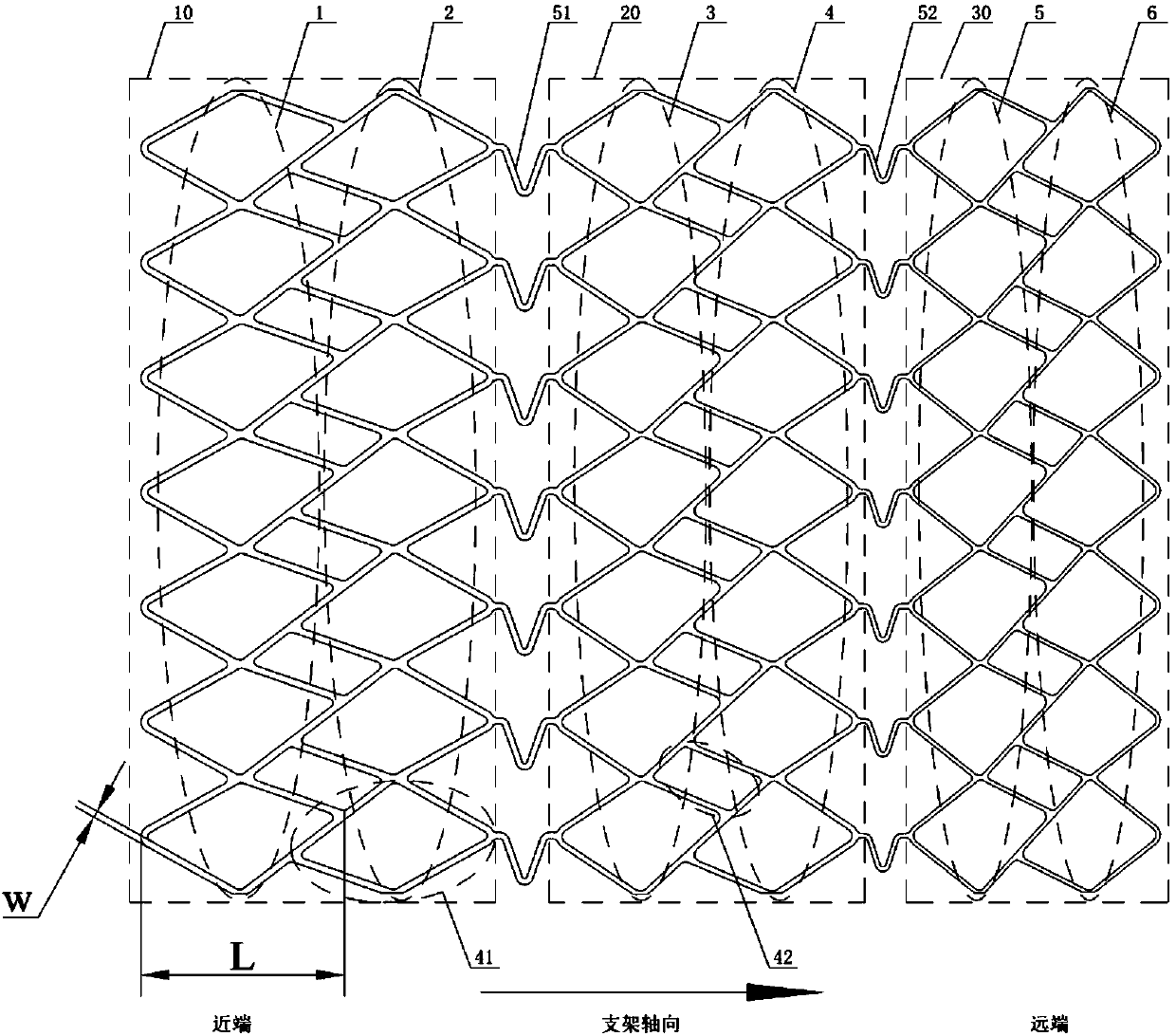
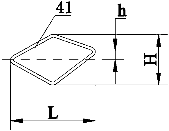
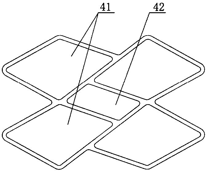
[0036] figure 1 Shown is an embodiment of the ladder-shaped stent suitable for tapered blood vessels according to the present invention: the blood vessel stent is a three-step stent, including 3 stent segments with different calibers, namely, the proximal stent segment 10, the middle stent segment The stent segment 20 and the distal stent segment 30 are connected by V-shaped connection units between adjacent stent segments. Wherein the proximal stent section 10 includes a first asymmetric hole unit 1 and a second asymmetric hole unit 2, the middle stent section 20 includes a third asymmetric hole unit 3 and a fourth asymmetric hole unit 4, and the distal stent section 30 includes Fifth asymmetric hole unit 5 and sixth asymmetric hole unit 6 . The proximal stent segment 10 is connected to the intermediate stent segment 20 through the first V-shaped connecting rib 51 , and the intermediate stent segment 20 is connected to the distal stent segment 30 through the second V-shaped ...

Embodiment example 2

[0042] Figure 4 Shown is another embodiment of the ladder-shaped stent suitable for tapered blood vessels according to the present invention: the blood vessel stent is a two-step stent, including two stent segments with different calibers, and the adjacent stent segments pass through M-shaped The connecting rib 53 is connected.

[0043] The two stent segments are respectively a proximal stent segment 10 and a distal stent segment 30, wherein the proximal stent segment 10 includes a first asymmetric hole unit 1, a second asymmetric hole unit 2 and a third asymmetric hole unit 3, and the far The end bracket section 30 includes a fourth asymmetric hole unit 4 , a fifth asymmetric hole unit 5 and a sixth asymmetric hole unit 6 .

[0044] In practical application, the length of each bracket segment of the ladder-shaped bracket can be adjusted by increasing or decreasing the number of asymmetric hole units in the bracket segment; Adapt to diseased blood vessels of different lengt...


PUM


Abstract

The invention provides a stepped stent applicable to a tapered blood vessel. The stent comprises a plurality of stent sections sequentially arranged in the axial direction of the stent; expansion diameters of the stent sections are different; the adjacent stent sections are connected through connecting units; each stent section comprises a plurality of identical asymmetric hole units sequentially formed in the axial direction of the stent, each asymmetric hole unit comprises a plurality of non-parallel quadrangular holes in identical shapes, and the non-parallel quadrangular holes in the same asymmetric hole unit are sequentially connected at vertexes; every two adjacent non-parallel quadrangular holes of every two adjacent asymmetric hole units share a part of one edge, so that every four adjacent non-parallel quadrangular holes form staggered support rings. The stent is used for the tapered lesion blood vessel, the near-end wall attachment performance and the far-end expansion performance are good, the radial rigidity of the stent is improved, the blood flow environment is improved, and bad consequences caused by the high metal coverage rate are reduced.

Description

technical field [0001] The invention belongs to the field of medical equipment, and relates to a balloon-expandable vascular stent for treating conical diseased blood vessels through percutaneous coronary artery vascular stent intervention. Background technique [0002] As a major killer of human health, cardiovascular disease has attracted more and more attention. Due to abnormal blood metabolism, lipids are deposited on the arterial intima and gradually accumulate into plaques, which hinder blood flow and cause cardiac ischemia, which seriously affects the metabolism of the human body and endangers human health. In the middle of the last century, interventional surgery began to enter this treatment field, and has attracted widespread attention for its minimally invasive, efficient and safe. At present, intravascular stent interventional surgery has become the main way to treat vascular occlusion diseases. [0003] At present, the existing metal stent is a hollow round str...

Claims


Application Information

Patent Timeline
Patent Type & Authority Patents(China)
IPC IPC(8): A61F2/91
CPCA61F2/91A61F2210/0061A61F2230/0002
Inventor 申祥邓永泉纪松谢中敏
Owner JIANGSU UNIV
Why Eureka
Eureka Blog
Learn More