Hot runner injection nozzle tip structure

A technology of hot runner and nozzle body, which is applied in the field of hot runner injection nozzle tip structure, which can solve the problems of easy wear and tear, and achieve the effects of high corrosion resistance, high wear resistance, good production effect and economic benefits

Inactive Publication Date: 2016-12-21
GUANGDONG YUDO HOT RUNNER SYST
View PDF5 Cites 7 Cited by
  • Summary
  • Abstract
  • Description
  • Claims
  • Application Information

AI Technical Summary

Problems solved by technology

However, if the nozzle tip of this material is applied to high-corrosion and high-wear-resistant plastic materials

Method used


Image

  • Hot runner injection nozzle tip structure
  • Hot runner injection nozzle tip structure

Examples


Embodiment Construction

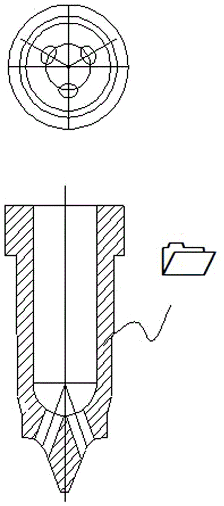
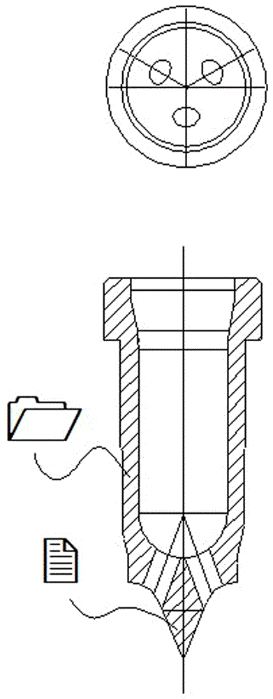
[0010] See attached figure 2 , a tip structure of a hot runner injection nozzle, comprising an injection nozzle body 1 and a nozzle tip 2, and the nozzle tip 2 and the injection nozzle body 1 are solidly connected as one.

[0011] The tip 2 is 3D printed.

[0012] The tip 2 is composite ceramics.

[0013] When using the present invention, since the nozzle tip 2 of high wear-resistant and corrosion-resistant material is printed and attached to the injection nozzle body 1 made of beryllium copper through 3D printing technology, the nozzle tip 2 of this material has high wear resistance and high corrosion resistance. And good thermal conductivity, resulting in good production effect and economic benefits.


PUM


Abstract

The invention relates to the technical field of thermoplastic processing, in particular to a hot runner injection nozzle tip structure. According to the technical scheme, the hot runner injection nozzle tip structure comprises an injection nozzle body and a nozzle tip, and the nozzle tip and the injection nozzle body are integrally fixed. The nozzle tip is formed through 3D printing. The nozzle tip is a composite ceramic. According to the hot runner injection nozzle tip structure, the nozzle tip made of a material with high abrasion resistance and high corrosion resistance is attached to the injection nozzle body made of beryllium copper in a printing manner through a 3D printing technology, the high abrasion resistance, high corrosion resistance and good heat conductivity of the nozzle tip made of the material with the high abrasion resistance and high corrosion resistance are enhanced, and the very good production effect and economic benefits are generated.

Description

technical field [0001] The invention relates to the technical field of thermoplastic processing, in particular to a tip structure of a hot runner injection nozzle. Background technique [0002] Hot runner processing technology is to ensure that the plastic in the runner and gate remains molten for injection molding by heating. The current processing of hot runner products is mainly based on traditional technology, while the existing injection nozzle 1 tip structure uses a single beryllium copper material, such as figure 1 As shown, this material has good thermal conductivity and is widely used in the tip structure of the hot runner industry. However, if the tip of this material is applied to highly corrosive and wear-resistant plastic materials during processing, it is easy to be worn, so this problem has become a major difficulty in the hot runner industry. Contents of the invention [0003] The purpose of the present invention is to overcome the disadvantages of the ab...

Claims


Application Information

Patent Timeline
IPC IPC(8): B29C45/27B29C33/38
CPCB29C45/278B29C33/3828B29C33/3842
Inventor 李象烈
Owner GUANGDONG YUDO HOT RUNNER SYST
Why Eureka
Try Eureka