

Filter flange fast and convenient to connect
A technology for filtering flanges and flanges, which is applied to flange connections, passing elements, pipes/pipe joints/fittings, etc., can solve the problems of slowing down the construction progress, time-consuming and laborious, waste of manpower and material resources, etc., to speed up the project progress, The model is accurate and the effect of removing impurities
- Summary
- Abstract
- Description
- Claims
- Application Information
AI Technical Summary
Problems solved by technology
Method used
Image

Examples
Embodiment 1
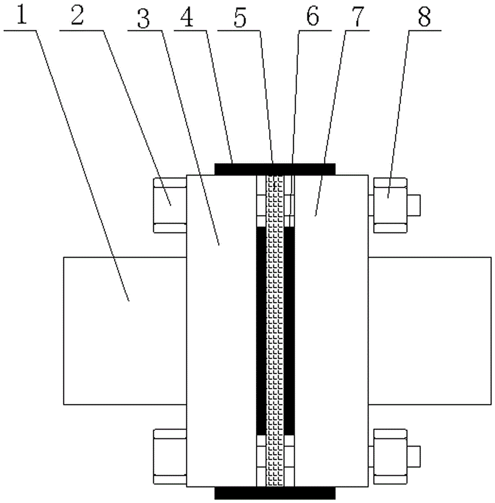
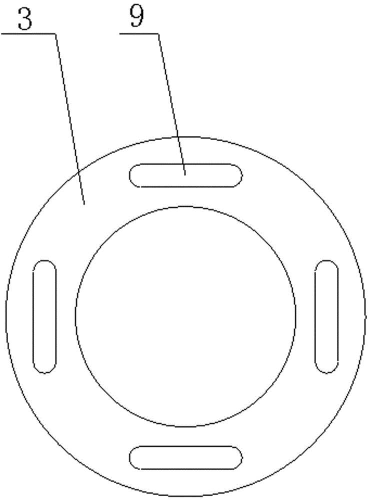
[0054] The fast connection filter flange of this embodiment, such as figure 1 and 2 As shown, including the first flange 3, the second flange 7, the circular strainer 5, the fastening bolts 2 and the nuts 8, the corresponding positions of the first flange 3, the second flange 7 and the circular strainer 5 Four waist-shaped holes 9 are provided respectively, and the four waist-shaped holes 9 are symmetrically arranged in pairs. The fastening bolts 2 pass through the first flange 3, the circular filter screen 5 and the second flange 7 in turn, and are threaded with the nut 8. A sealing gasket 6 is arranged between the first flange 3 and the second flange 7, and there are two sealing gaskets 6, and the two sealing gaskets 6 are arranged on both sides of the circular filter screen 5 respectively, the first flange 3 and the second flange 7 The opposite sides of the two flanges 7 are respectively equipped with pipe joints 1 , and the joints of the first flange 3 and the second flan...
Embodiment 2
[0094] The fast connection filter flange of this embodiment is basically the same as that of Embodiment 1, except that the mass percentages of the components in the first flange 3 and the second flange 7 are: C: 0.31%, Al: 2.23% , Zn: 0.55%, Si: 0.29%, Mn: 0.93%, S: ≤0.030%, P: ≤0.030%, Cr: 0.08%, Ni: 0.19%, Cu: 0.24%, V: 0.03%, Mo: 0.03%, Ti: 0.36%, B: 0.04%, Pd: 0.09%, Pt: 0.13%, W: 0.19%, Ta: 0.05%, Nd: 0.18%, Ce: 0.03%, Eu: 0.05%, Lu: 0.26%, Au: 0.36%, Ag: 0.63%, Ga: 0.03%, Y: 0.14%, Sn: 0.49%, Zr: 0.23%, Re: 0.07%, Os: 0.06%, Hf: 0.21%, Bi: 0.33%, glass fiber: 0.31%, calcium oxide: 0.52%, light calcium carbonate: 0.36%, talcum powder: 0.32%, magnesium oxide: 0.27%, and the balance is Fe.
PUM
 Abstract
Description
Claims
Application Information