Coating mechanism for metalized film processing

A metallized film, evaporation coating technology, applied in metal material coating process, sputtering coating, ion implantation coating and other directions, can solve the problem of low surface temperature of insulating film, can not meet the three-dimensional adjustment, inconvenient automatic adjustment and other problems, to achieve the effect of adjustable coating thickness

Inactive Publication Date: 2016-12-21
铜陵市铜创电子科技有限公司
View PDF5 Cites 2 Cited by
  • Summary
  • Abstract
  • Description
  • Claims
  • Application Information

AI Technical Summary

Problems solved by technology

[0003] (2) If the existing vacuum coating machine is directly coated by the coating mechanism after being fed by the feeding device, the temperature on the surface of the insulating film is low and the stability of the coating is poor
However, most of the preheating devices are fixed and cannot be adjusted, resulting in uneven preheating
Although a vacuum coating equipment disclosed in the prior art such as patent application 201520245919.7 provides a heating device that can move along an arc guide rail and realizes the angle adjustment of the heating device through a metal flexible hose, the structure uses metal flexible The physical properties of the hose itself are bent, which is inconvenient to realize automatic adjustment; in addition, the movement of the arc-shaped guide rail can drive the movement of the heating device to achieve linear two-dimensional adjustment, which cannot meet three-dimensional three-dimensional adjustment, and it is difficult to realize the control of preheating intensity. Preheating uniformity also needs to be improved

Method used


Image

  • Coating mechanism for metalized film processing
  • Coating mechanism for metalized film processing
  • Coating mechanism for metalized film processing

Examples


Embodiment Construction

[0023] In order to further describe the present invention, it will be further described in the following embodiments.

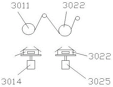
[0024] Such as figure 1 As shown, the coating mechanism includes a first evaporation coating device, including a first evaporation drum 3011, a first evaporation boat 3012. The first evaporation boat 3012 is arranged below the first evaporation drum 3011. The top opening area of ​​the first evaporation boat 3012 is provided with a first movable plate assembly that controls the size of the opening of the first evaporation boat 3012.

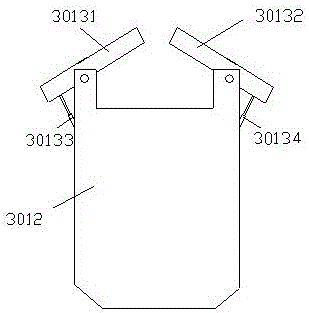
[0025] Such as figure 2 As shown, as a preferred solution: the first movable panel assembly includes a first left movable panel 30131, a first right movable panel 30132, a first left telescopic device 30133, and a first right telescopic device 30134. The lower end of the first left movable plate 30131 is hinged to the end of the top of the first evaporation boat 3012, and the higher end is the free end. The fixed end of the first l...


PUM


Abstract

The invention discloses a coating mechanism for metalized film processing. According to the coating mechanism for metalized film processing, a first evaporation coating device and a second evaporation coating device are sequentially arranged from front to back according to the technological process. The coating mechanism comprises the first evaporation coating device. The first evaporation coating device comprises a first evaporation coating drum and a first evaporation boat. The first evaporation boat is arranged below the first evaporation coating drum. The top opening area of the first evaporation boat is provided with a first movable plate assembly used for adjusting the size of an opening of the first evaporation boat. The second evaporation coating device comprises a second evaporation coating drum, a second evaporation boat and a shielding device. The second evaporation boat is arranged below the second evaporation coating drum. The top opening area of the second evaporation boat is provided with a second movable plate assembly used for adjusting the size of an opening of the second evaporation boat. The shielding device is used for limiting the width and the area of the fallen metal evaporated from the opening of the second evaporation boat on an insulated film. The coating mechanism for metalized film processing has the advantages of being suitable for processing of multiple types of films and achieving that the coating thickness is adjustable.

Description

Technical field [0001] The invention relates to the technical field of coating machines, in particular to a coating mechanism for metalized thin film processing. Background technique [0002] As the main component of the capacitor, the quality of the metalized film directly affects the service life of the capacitor. At present, metallized films are mainly prepared by vacuum coating machines, including an insulating film feeding mechanism, a coating mechanism, and a film winding mechanism after plating a metal layer. However, the prior art vacuum coating machine has the following shortcomings: [0003] (2) If the existing vacuum coating machine is directly coated by the coating mechanism after the feeding device is fed, the temperature of the insulating film surface is lower and the coating stability is poor. The solution is to improve the interface effect of the surface by setting a preheating device. However, most of the preheating devices are fixed and not adjustable, resultin...

Claims


Application Information

Patent Timeline
Patent Type & Authority Applications(China)
IPC IPC(8): C23C14/24C23C14/56
CPCC23C14/24C23C14/243C23C14/562
Inventor 高文明
Owner 铜陵市铜创电子科技有限公司
Why Eureka
Try Eureka