A clamp system and a sewing machine with the clamp system

A technology of clamping mechanism and clamping parts, which is applied to sewing machine components, leather product sewing machines, control devices for sewing machines, etc.

A technology of clamping mechanism and clamping parts, which is applied to sewing machine components, leather product sewing machines, control devices for sewing machines, etc.

CN106245239AActive Publication Date: 2016-12-21JUKI CORP

Image

  • A clamp system and a sewing machine with the clamp system
  • A clamp system and a sewing machine with the clamp system
  • A clamp system and a sewing machine with the clamp system

Examples


Embodiment Construction

[0090] [Overall structure of sewing machine]

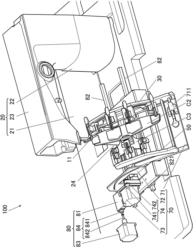
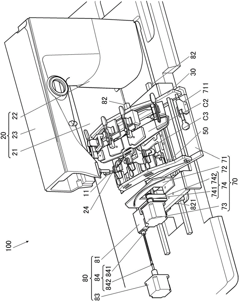
[0091] Below, based on Figure 1 to Figure 9 , the sewing machine 100 as an embodiment of the present invention will be described. The sewing machine 100 is an automatic sewing machine that uses first and second clamping mechanisms 30 and 50 suitable for holding a curved object to perform needle drop at an arbitrary position according to a predetermined sewing pattern.

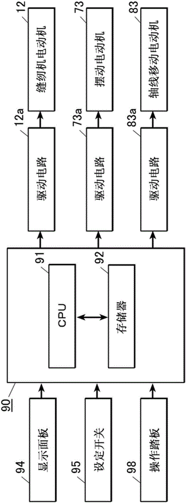
[0092] figure 1 and figure 2 It is a perspective view which omits the structure of a part of the sewing machine 100, image 3 It is a block diagram showing the control system of the sewing machine.

[0093] In the following description, the following case is exemplified, that is, for the shoe upper C1 of a ring-shaped shoe (refer to Figure 5 ), the reinforcement material C2 and the label C3 as the sewing object are sewn at the heel portion.

[0094] The above-mentioned sewing machine 100 is provided with: a needle bar which holds a sewing needle at a lower...


PUM


Abstract

The invention can sew a plurality of types of curved surfaces. A clamp system comprises a plurality of clamp units (40) including a pair of clamping parts (41, 42) clamping sewed objects (C1, C2) and a supporting block (44) supporting the pair of the clamping parts, and a frame (31) mounting the supporting block and provided with one or more slot mounting holes (32-35) formed along a curve or a plurality of straight lines, wherein the plurality of straight lines are along the curve, and the plurality of clamp units are mounted in a manner that positions can be adjusted along the mounting hole(s) of the frame.

Description

technical field [0001] The present invention relates to a clamp mechanism when sewing a curved surface-shaped object and a sewing machine equipped with the clamp mechanism. Background technique [0002] For example, in the sewing of shoes, the toe part and the heel part of the upper of the shoe composed of left and right parts are sewn into a ring shape, and seaming members such as labels and reinforcing materials are sewn on the outside of the heel part. [0003] The heel part of the upper of the shoe needs to be processed into a curved shape in accordance with the shape of the heel of the foot. However, in order to sew the upper in a curved state, a so-called high sewing table (post bed) sewing machine is used. In the table sewing machine, a kettle and a needle plate are installed upright from the upper surface of the sewing machine base so that the fabrics on both sides of the sewing position can be bent. [0004] In addition, sewing performed by automatic feeding along ...

Claims


Application Information

Patent Timeline
21 Dec 2016
Publication
CN106245239A
IPC
D05B35/00; D05B69/00
CPC
D05B35/00; D05B69/00; D05B15/02; D05B35/02; D05B39/00
Inventors
恒川η₯ζ ‘; ηŽ‰ζœ¨ε“δΈ€