Rail detection trolley

A track detection and trolley technology, used in tracks, track laying, track maintenance, etc., can solve problems such as inability to achieve online detection, unsuitable handheld devices or hand-pushed trolleys, and inability to meet the requirements of rail detection accuracy.

Active Publication Date: 2016-12-21
CRCC HIGH TECH EQUIP CORP LTD
View PDF8 Cites 3 Cited by
  • Summary
  • Abstract
  • Description
  • Claims
  • Application Information

AI Technical Summary

Problems solved by technology

[0005] In order to verify whether the repair of the rail by the rail grinding car / milling car meets the requirements, it is necessary to test the quality of the repaired rail, especially the track profile and corrugation. At present, the industry mainly uses high-precision handheld devices or hand-push trolleys Measure the rail quality after the rail grinding car / milling car works, but the handheld device can only achieve single-point measurement, and the handheld device or hand-push trolley is not suitable for places where people are not easy to enter, such as subway tunnels. Therefore, a A device capable of on-line measurement of rail quality
For rail grinding vehicles, due to the low grinding accuracy, some rail inspection vehicles on the market can detect the quality of the polished rails. However, due to the high precision of rail milling vehicles, the existing rails The inspection vehicle cannot meet the rail inspection accuracy requirements after its operation
[0006] The Chinese utility model patent with the application number 201520096195.4 discloses a track detection trolley, which includes a car body, the car body includes a box-shaped frame and a main beam, and the box-shaped frame is a symmetrical rigid structure, including two side beams and two parallel opposite side panels, the ends of each side beam are respectively located above the two side panels and perpendicular to them; the main beam is the central axis of the vehicle body, and the two ends are connected to the center Connected, parallel to the side beam; the rolling wheel is a three-point support structure, the axial direction is consistent with the main beam, two inner rail wheels and one outer rail wheel are located on the same horizontal plane, and the inner rail wheel is relative to the main beam The beams are symmetrically distributed at both ends of one side plate, and the outer rail wheel is located in the center of the other side plate. The whole car body is not easy to deform, has high torsional rigidity, and can stably support the power supply, various sensors, and three rolling wheels. The base surface is unique, and the above structure improves the accuracy of detection data, but cannot realize online detection

Method used


Image

  • Rail detection trolley
  • Rail detection trolley
  • Rail detection trolley

Examples


Embodiment Construction

[0039] In this paper, for the convenience of explanation, the left side of the driving direction of the track detection trolley following the rail repair vehicle is defined as left, the right side of the driving direction of the track detection trolley following the rail repair vehicle is defined as right, and the direction of the rail to the outside is defined as Outside, the direction of the rail to the inside is defined as inside.

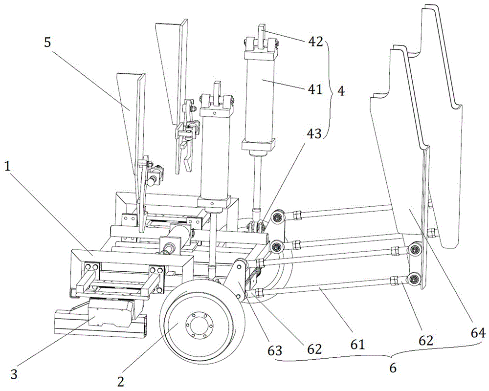
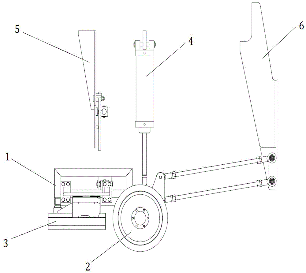
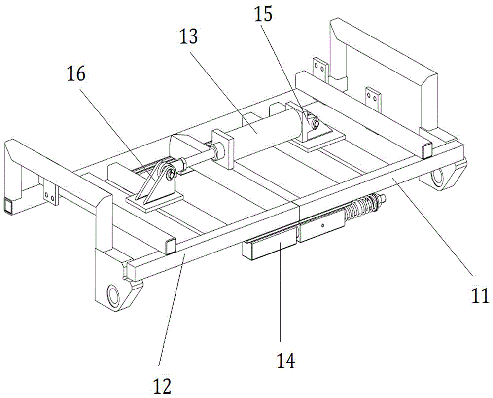
[0040] Attached below Figure 1-Figure 4 The preferred embodiment of the track detection trolley provided by the present invention is described.

[0041] figure 1 It is the front view of a track detection trolley provided by the embodiment of the present invention, figure 2 A side view of a track inspection trolley provided by an embodiment of the present invention, image 3 It is a schematic diagram of the detailed structure of a chassis 1 of a track detection trolley provided by an embodiment of the present invention. Such as figure 1 an...


PUM


Abstract

A rail detection trolley comprises an underframe, wheels, measurement devices, lifting devices, locking devices and traction devices, wherein the two wheels are mounted on the left side and the right side of the underframe respectively, connected with the underframe and used for supporting the trolley on steel rails when the rail detection trolley is put down, so that the rail detection trolley can perform moving operation on the steel rails; the two measurement devices are mounted right above a left steel rail and a right steel rail respectively, fixed on the underframe and used for detecting the rail profiles and corrugations of the steel rails on line in a non-contact detection manner; the lifting devices are used for lifting the underframe to a preset height above the rails or putting the underframe on the steel rails; the locking devices are used for locking the underframe when the underframe is lifted to the preset height above the rails; the traction devices are mounted on the front side of the underframe, fixedly connected with the underframe and used for pulling the rail detection trolley put on the steel rails to move with a steel rail repairing vehicle.

Description

technical field [0001] The invention relates to the technical field of engineering equipment, in particular to a track detection trolley used for rail repair vehicles. Background technique [0002] In recent years, with the increase of rail transit operation volume and the improvement of operating speed, the problem of rail surface damage has become more and more prominent. If the rail surface damage cannot be repaired in time and effectively, it will seriously affect the driving safety and the service life of the rail. In order to ensure the safety, stability and comfort of train operation, improve the wheel-rail contact state, reduce wheel-rail noise, increase the service life of the rail, and slow down the damage expansion speed of the rail surface, a fast and efficient mobile on-line repair must be adopted Technology to eliminate the surface damage of the rail and restore the good profile and smoothness of the rail. [0003] At present, rail grinding vehicles are widely...

Claims


Application Information

Patent Timeline
IPC IPC(8): E01B31/12E01B35/00
CPCE01B31/12E01B35/00E01B2203/16
Inventor 史天亮卫明郭关柱
Owner CRCC HIGH TECH EQUIP CORP LTD
Why Eureka
Try Eureka