Scaffold fastener slipping alarm device and installation method thereof

An alarm device and scaffolding technology, which is applied to the accessories of scaffolding, building structure support, building structure support, etc., can solve the problems of casualties and other problems, and achieve the effect of preventing alarm device failure or false alarm, easy operation, and clear steps

Active Publication Date: 2016-12-21
CHINA MCC17 GRP
View PDF7 Cites 4 Cited by
  • Summary
  • Abstract
  • Description
  • Claims
  • Application Information

AI Technical Summary

Problems solved by technology

As a result, there were no obvious early warning measures before the collapse of the scaffolding on the outer wall, resulting in a large number of casualties when the scaffolding collapsed

Method used


Image

  • Scaffold fastener slipping alarm device and installation method thereof
  • Scaffold fastener slipping alarm device and installation method thereof

Examples


Embodiment 1

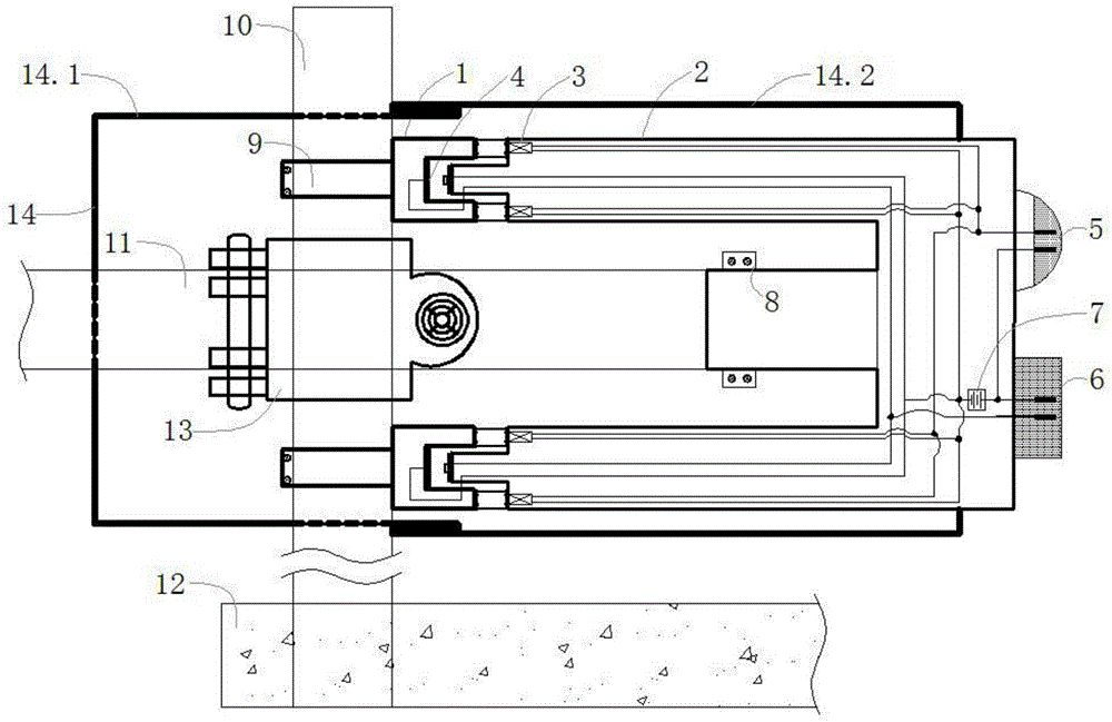
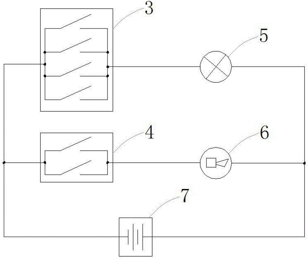
[0038] Scaffold fastener slipping alarm device, such as figure 1 and figure 2 As shown, it includes a vertical bar 10 and a cross bar 11 and a fastener 13 for fastening the vertical bar 10 and the cross bar 11. The bottom of the vertical bar 10 is fixed in the main concrete structure 12, and it also includes a limiting device and a warning device. The device includes an E-shaped sleeve 2 fixed to the end of the cross bar 11 through the first buckle 8. The limit device also includes a U-shaped sleeve 1 fixed to the side of the vertical pole 10 through the second buckle 9. The E-shaped sleeve 2 includes two upper and lower A protruding head at the end of a protruding section, the top of the protruding head is provided with a first contact, the protruding head is adapted to the cavity of the U-shaped sleeve 1, and the upper surface of the bottom of the cavity of the U-shaped sleeve 1 is provided with a second contact, the first The contact and the second contact form the two po...

Embodiment 2

[0053] Scaffold fastener slipping alarm device, such as figure 1 and figure 2 As shown, it includes a vertical bar 10 and a cross bar 11 and a fastener 13 for fastening the vertical bar 10 and the cross bar 11. The bottom of the vertical bar 10 is fixed in the main concrete structure 12, and it also includes a limiting device and a warning device. The device includes an E-shaped sleeve 2 fixed to the end of the cross bar 11 through the first buckle 8. The limit device also includes a U-shaped sleeve 1 fixed to the side of the vertical pole 10 through the second buckle 9. The E-shaped sleeve 2 includes two upper and lower A protruding head at the end of a protruding section, the top of the protruding head is provided with a first contact, the protruding head is adapted to the cavity of the U-shaped sleeve 1, and the upper surface of the bottom of the cavity of the U-shaped sleeve 1 is provided with a second contact, the first The contact and the second contact form the two po...


PUM


Abstract

The invention discloses a scaffold fastener slipping alarm device comprising a limiting device and a warning device; the limiting device comprises an E-shaped sleeve fixed on an end of a cross bar through a first buckle; the limiting device comprises an U-shaped sleeve fixed on a side surface of a vertical rod through a second buckle; the warning device comprises a first warning device and a second warning device which are in parallel connection with a power supply; two sets of touch control switches are in parallel and are in series connection with the power supply and a second warning device; four sets of pressure switches are in parallel and are in series connection with the power supply and the first warning device; The invention also discloses an installation method for the scaffold fastener slipping alarm device. Glass beads of the installation method effectively protect the relative position of the E-shaped sleeve and the U-shaped sleeve; the invention provides a step alarming scheme, which effectively solves the problem that there is no warning device for the scaffold fastener slipping. The installation method of the invention has the advantages of clear steps and easy operation. The invention effectively solves the problem that there is no warning device for the scaffold fastener slipping.

Description

technical field [0001] The invention belongs to the field of construction engineering safety devices, in particular to a sliding alarm device for scaffold fasteners. Background technique [0002] At present, scaffolding is widely used in building construction, but there are currently overloaded frames, unqualified frame tubes or fasteners, irregular erection, etc., and the level of external frame construction is uneven. [0003] On October 8, 2011, at the construction site of Kaixuan Building in the northern suburbs of Xi'an, a cantilevered scaffolding of a 30-story high-rise under construction collapsed. Buried pressure, 7 of them died on the spot and 5 were injured. [0004] On November 19, 2012, Jiangsu Fengyi Construction and Installation Engineering Co., Ltd. had a local scaffolding collapse accident during the concrete pouring construction of the two-story building in Xingbing Town, Qianchaohu City. 9 workers were buried, and 6 workers died and 3 were injured on the ...

Claims


Application Information

Patent Timeline
IPC IPC(8): E04G5/00
CPCE04G5/001
Inventor 舒营
Owner CHINA MCC17 GRP
Why Eureka
Try Eureka