
Milling device and method for full-section cantilever roadheader for tunnel and underground engineering

A cantilever roadheader and underground engineering technology, applied in tunnels, earth-moving drilling, mining equipment, etc., can solve problems such as excessive measures, casualties, equipment, and face instability, and achieve improved work efficiency and a high degree of automation. , The effect of saving excavation costs

Inactive Publication Date: 2019-10-18
CHINA RAILWAY CONSTR CORP LTD
View PDF6 Cites 0 Cited by
  • Summary
  • Abstract
  • Description
  • Claims
  • Application Information

AI Technical Summary

Problems solved by technology

However, for the full-section construction of the cantilever roadheader, due to the limitation of the construction space and other factors, the above measures cannot be well applied.
Moreover, the application of the above-mentioned face instability prevention and control measures is ahead of theoretical research, and many reinforcement technologies have shortcomings such as unclear mechanisms and lack of theoretical basis for design.
This often leads to two results: either the measures are too strong, resulting in waste; or the instability of the face cannot be effectively controlled, resulting in casualties and equipment losses
The above technologies are given in the form of the allowable convergence or allowable rate of the surrounding area. These are obtained through monitoring and measurement methods and regression analysis after the tunnel is excavated to form a cavern. It can only roughly reflect the tunnel Stability of the cavern after excavation

Method used


Image

  • Milling device and method for full-section cantilever roadheader for tunnel and underground engineering
  • Milling device and method for full-section cantilever roadheader for tunnel and underground engineering
  • Milling device and method for full-section cantilever roadheader for tunnel and underground engineering

Examples


Embodiment Construction

[0029] The following will clearly and completely describe the technical solutions in the embodiments of the present invention with reference to the accompanying drawings in the embodiments of the present invention. Obviously, the described embodiments are only some, not all, embodiments of the present invention. Based on the embodiments of the present invention, all other embodiments obtained by persons of ordinary skill in the art without making creative efforts belong to the protection scope of the present invention.

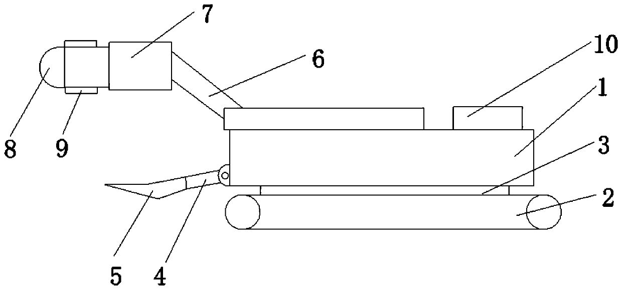
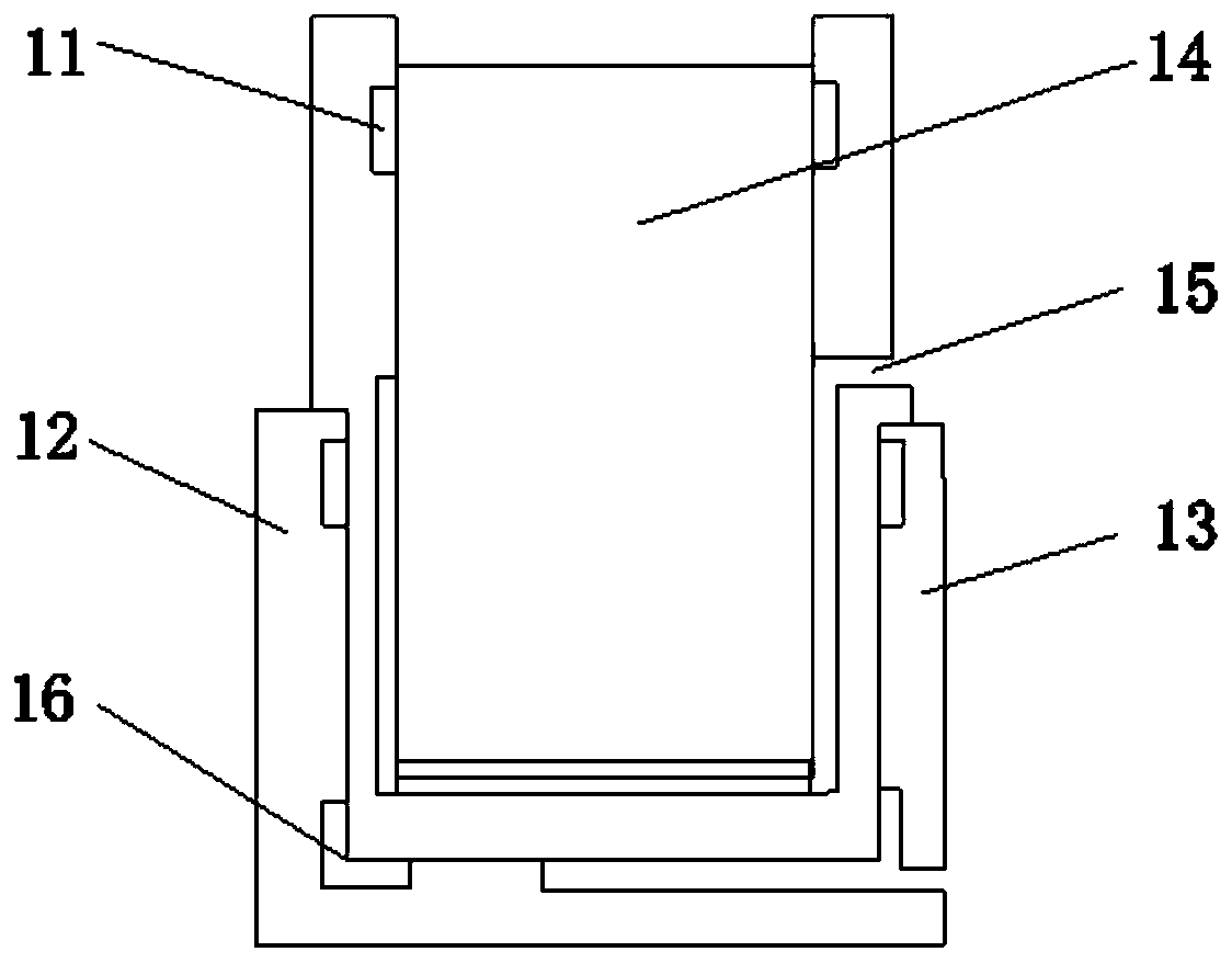
[0030] see Figure 1-2 , the present invention provides a technical solution: a full-section cantilever boring machine milling device for tunnels and underground engineering, including a fuselage 1, a running part 2 is provided at the bottom of the fuselage 1, and the running part 2 and the fuselage 1 are The lower part of the front end of the fuselage 1 is connected to the shovel plate 5 through the first cylinder 4, the upper end of the front end of the fuse...


PUM


Abstract

The invention discloses a tunnel and underground engineering full cross-section cantilever tunneling machine milling and excavating device and method. The device comprises a machine body. A walking portion is arranged at the bottom of the machine body. The machine body and the walking portion are connected through a rotating mechanism. The lower portion of the front end of the machine body is connected with a shoveling plate through a first air cylinder. The upper end of the front end of the machine body is connected with a cutting portion through a second air cylinder. The front end of the cutting portion is provided with a milling and excavating head. The milling and excavating head is of a hemispherical structure. The two sides of the cutting portion are provided with infrared distancers. An electrical control system is arranged on the machine body. The device is simple in structural principle, capable of effectively limiting compressional deformation and converging deformation of an excavated rock body on an excavating face in front of the excavating face, advanced supporting is not performed on the condition that the surrounding rock level is not poor, the tunnel excavating cost is saved, and the excavating efficiency of the cantilever tunneling machine is improved.

Description

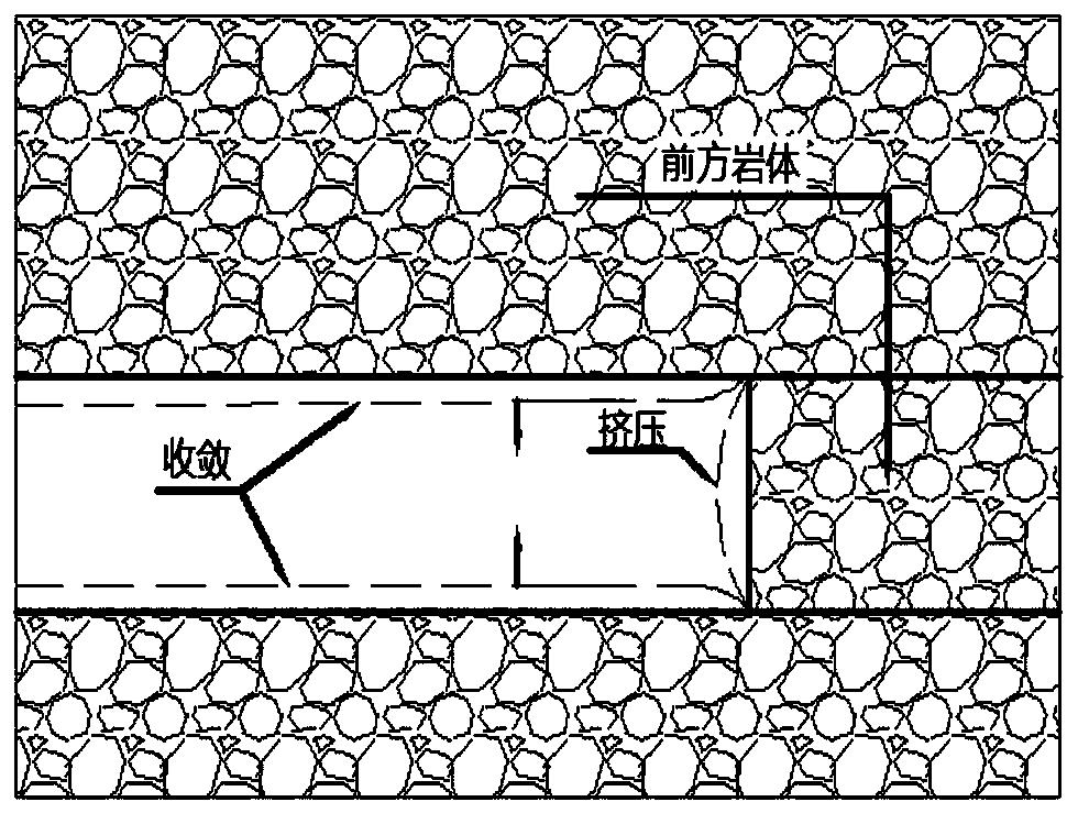
technical field [0001] The invention relates to the technical field of cantilever roadheader milling and digging, in particular to a full-section cantilever roadheader milling device and method for tunnels and underground engineering. Background technique [0002] At present, for the stability of the tunnel face, the typical analogy analysis method is mainly used to understand and deal with the stability of the surrounding rock support system in underground engineering. However, there is still a lack of clear understanding and definite construction of how to effectively and timely prevent the tunnel face from being unstable under complex and changeable geology, engineering structures and construction conditions before excavation and in the initial stage of support after excavation. method. Before the excavation of the tunnel, the geological layer in front of the tunnel face is detected to guide the construction, and the rock samples are obtained by core drilling in front of...

Claims


Application Information

Patent Timeline
Patent Type & Authority Patents(China)
IPC IPC(8): E21D9/11E21D9/12E21D9/00
Inventor 陈发达李辉高志勇田晓旭宋战平冯卫东吴海宝孔祥平周延王祥王辉梁小波刘勇黄松
Owner CHINA RAILWAY CONSTR CORP LTD
Learn More