Cooperating structure of a compressor and its rollers and sliding vanes

A technology of matching structure and compressor, applied in the field of compressor, can solve the problems of small difference between discharge pressure and suction pressure, small suction pressure and discharge pressure of compressor, abnormal noise of compressor, etc., so as to increase friction force. , the effect of maintaining followability, increasing contact length and contact area

Active Publication Date: 2019-08-23
GREE ELECTRIC APPLIANCES INC +1
View PDF8 Cites 0 Cited by
  • Summary
  • Abstract
  • Description
  • Claims
  • Application Information

AI Technical Summary

Problems solved by technology

However, under certain low-frequency operating conditions, the suction pressure and discharge pressure of the compressor are small, and the difference between the discharge pressure and suction pressure is small. The rollers cannot keep track, and the performance is that the compressor makes a "da da da" abnormal sound
[0004] Therefore, how to solve the problem that the sliding plate and the roller are easily separated in the prior art has become an important technical problem to be solved by those skilled in the art

Method used


Image

  • Cooperating structure of a compressor and its rollers and sliding vanes
  • Cooperating structure of a compressor and its rollers and sliding vanes

Examples


Embodiment Construction

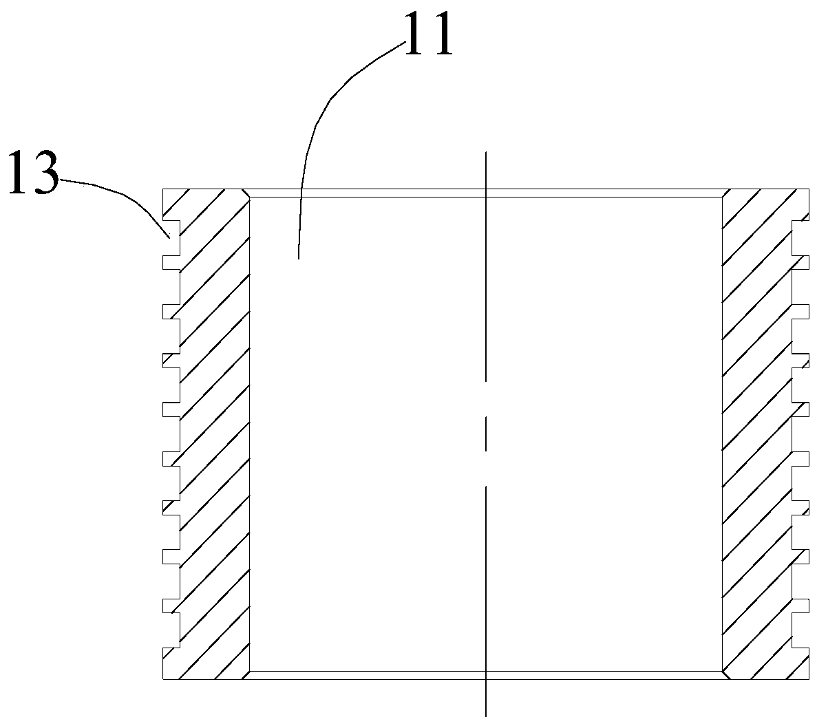
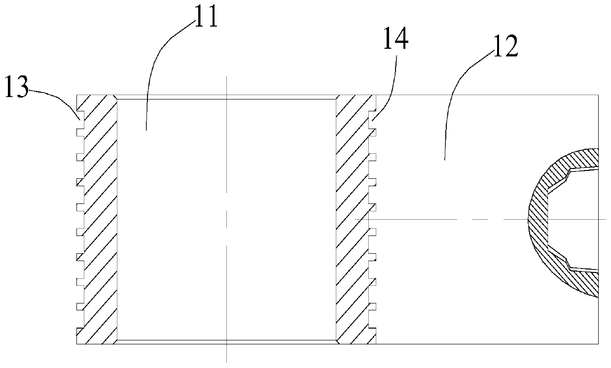
[0020] The purpose of this specific embodiment is to provide a cooperation structure between the roller and the sliding vane of the compressor, which can avoid the problem that the sliding vane and the roller are detached in the prior art. The purpose of this specific embodiment is also to provide a compressor including the cooperation structure of the above-mentioned rollers and sliding vanes.

[0021] Hereinafter, an embodiment will be described with reference to the drawings. In addition, the examples shown below do not limit the content of the invention described in the claims in any way. In addition, all the contents of the configurations shown in the following embodiments are not limited to be essential to the solutions of the invention described in the claims.

[0022] Please refer to Figure 1-Figure 2 , the cooperation structure between the roller 11 and the sliding plate 12 of the compressor provided in this specific embodiment, wherein an annular protrusion (not s...


PUM


Abstract

The invention discloses a compressor and a matching structure of a roller and a sliding plate of the compressor. According to the matching structure of the roller and the sliding plate, the outer circumferential face of the roller is provided with annular protrusions or annular grooves extending in the circumferential direction; and the end, making contact with the roller, of the sliding plate is provided with grooves matched with the annular protrusions, or protrusions matched with the annular grooves. In this way, the matching structure of the roller and the sliding plate of the compressor, the problem that in the prior art, a sliding plate and a roller are separated can be avoided.

Description

technical field [0001] The invention relates to the technical field of compressors, more specifically, to a compressor and a matching structure of rollers and sliding vanes thereof. Background technique [0002] The rotary compressor includes components such as crankshaft, roller, cylinder and sliding vane. The roller is installed on the eccentric part of the crankshaft and rotates concentrically with the eccentric part of the crankshaft. The inner wall of the cylinder is provided with a sliding vane installation groove, and the sliding vane is installed on the and the sliding piece installation groove is provided with an elastic member to ensure that the sliding piece can be elastically expanded and contracted in the sliding piece installation groove. The sliding plate can slide freely and is always in contact with the roller under the action of elastic force, thereby separating the closed cavity formed by the cylinder and the roller into an air suction chamber and an exhau...

Claims


Application Information

Patent Timeline
Patent Type & Authority Patents(China)
IPC IPC(8): F04C18/356F04C29/00
CPCF04C18/356F04C29/00F04C2240/20
Inventor 伍文轩范少稳
Owner GREE ELECTRIC APPLIANCES INC
Why Eureka
Try Eureka