An improved centrifugal fan rotating stall experimental device and its detection method

A rotating stall and experimental device technology, applied in mechanical equipment, engine control, machine/engine, etc., can solve the problems of blade high stress point fatigue, surge, accident hidden danger, etc., to reduce the interference signal component, improve the accuracy, The effect of improving uniformity

Inactive Publication Date: 2017-10-13
NORTH CHINA ELECTRIC POWER UNIV (BAODING)
View PDF1 Cites 0 Cited by
  • Summary
  • Abstract
  • Description
  • Claims
  • Application Information

AI Technical Summary

Problems solved by technology

After the rotating stall occurs, there are one or several stall clusters rotating in the circumferential direction inside the impeller, whose rotation speed is lower than the rotation speed of the impeller, which will generate additional aerodynamic load and aerodynamic noise, and may induce fatigue and The fracture problem affects the application range of the centrifugal fan
In addition, the phenomenon of rotating stall may lead to surge, causing vibration of the fan body and connecting pipes, resulting in potential accidents
However, in the prior art, the experimental device for rotating and stalling the centrifugal fan cannot simulate the whole process of the running state of the fan. Chinese invention patent CN103410762 B discloses a rotating and stalling control device and method for a centrifugal fan. Based on this device, the inventor, Developed a stall test device

Method used


Image

  • An improved centrifugal fan rotating stall experimental device and its detection method
  • An improved centrifugal fan rotating stall experimental device and its detection method
  • An improved centrifugal fan rotating stall experimental device and its detection method

Examples


Embodiment Construction

[0029] The standard parts used in the present invention can be purchased from the market, and the special-shaped parts can be customized according to the instructions and the accompanying drawings. The specific connection methods of each part adopt mature bolts, rivets, welding in the prior art , pasting and other conventional means, will not be described in detail here.

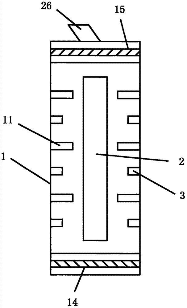
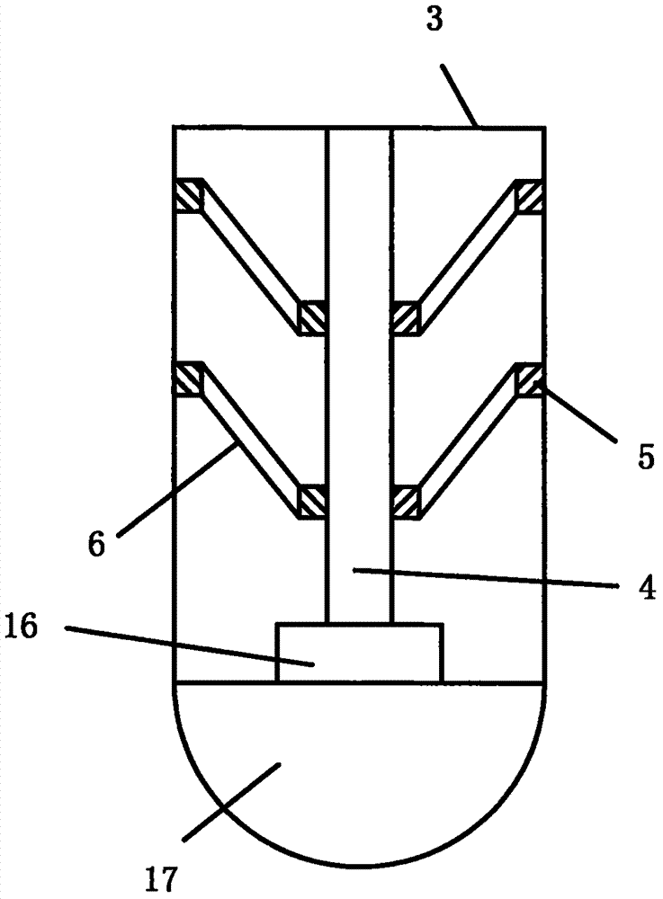
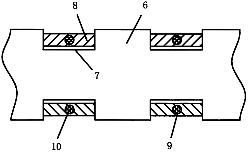
[0030] refer to Figure 1-7 , this embodiment includes a volute 1, an impeller 2 is installed inside the volute 1, several first nozzles 3 are evenly arranged on the inner surface of the volute 1, a base 16 is arranged at the bottom of the first nozzle 3, and the inside of the first nozzle 3 A first hydraulic rod 4 is installed in the axial direction, and the first hydraulic rod 4 is installed on the base 16. Several first baffles 6 are connected between the first hydraulic rod 4 and the inner wall of the first nozzle 3 through the first spring body 5 , the first baffle plate 6 is provided with a diversion ...


PUM


Abstract

The invention discloses an improved centrifugal fan rotating stall experiment device. The improved centrifugal fan rotating stall experiment device comprises a volute, wherein an impeller is mounted in the volute, a plurality of first nozzles are uniformly arranged on the inner side surface of the volute, the bottoms of the first nozzles are provided with bases, first hydraulic rods are axially arranged in the first nozzles, the first hydraulic rods are mounted on the bases, a plurality of first baffles are connected between the first hydraulic rods and the inner walls of the first nozzles through first springs, flow guiding grooves are formed in the first baffles, metal sheets are arranged in the flow guiding grooves in a sliding manner, first through holes are formed in the centers of the metal sheets, and rubber films are arranged on the first through holes; and a plurality of second baffles are further arranged on the inner side surface of the volute, the first nozzles and the second baffles are alternately arranged, a plurality of cross beams are arranged on the second baffles, and air bags are arranged between two connected cross beams. The invention further provides a centrifugal fan rotating stall detection method. The experiment device and the detection method can improve defects in the prior art and realize whole-process simulation on the rotating stall of a centrifugal fan.

Description

technical field [0001] The invention relates to the technical field of centrifugal fan rotational stall detection, in particular to an improved centrifugal fan rotational stall experimental device and a detection method thereof. Background technique [0002] Rotating stall is an unsteady flow phenomenon that occurs inside the impeller of the centrifugal fan under the condition of small flow. After the rotating stall occurs, there are one or several stall clusters rotating in the circumferential direction inside the impeller, whose rotation speed is lower than the rotation speed of the impeller, which will generate additional aerodynamic load and aerodynamic noise, and may induce fatigue and The fracture problem has affected the application range of the centrifugal fan. In addition, the phenomenon of rotating stall may lead to surge, causing vibration of the fan body and connecting pipes, resulting in potential accidents. However, in the prior art, the experimental device f...

Claims


Application Information

Patent Timeline
Patent Type & Authority Patents(China)
IPC IPC(8): F04D27/00
CPCF04D27/001F05D2270/022
Inventor 许小刚王惠杰吴正人孙玮
Owner NORTH CHINA ELECTRIC POWER UNIV (BAODING)
Why Eureka
Try Eureka