Supercharge Your Innovation With Domain-Expert AI Agents!

a fusible rod

A fusible sheet, fusing technology, applied in safety valves, engine components, balance valves, etc., can solve the problems of fusible sheet fusing lag, inability to play fire prevention, leakage, etc., and achieve the effect of small thermal expansion and deformation

Active Publication Date: 2018-06-19
CHONGQING SHUANGJIANG FIRE FIGHTING VENTILATION EQUIP MFG INSTALLATION
View PDF10 Cites 0 Cited by
  • Summary
  • Abstract
  • Description
  • Claims
  • Application Information

AI Technical Summary

Problems solved by technology

Although the existing fusible rods can meet the requirements of use to a certain extent, there is often the problem that the fusible rods cannot be blown under the set temperature conditions during use, that is, there is a long time lag in the melting of the fusible rods. question
[0003] Because fusible rods are often used in fire-fighting equipment such as fire dampers, if the fusible sheet 4 cannot be fused in time, people's lives and property will be threatened. The valve must be closed at a higher temperature, and due to thermal expansion and contraction caused by high temperature, the fire damper cannot be completely closed due to deformation at high temperature, that is, there is leakage, which will cause the fire damper to fail. For the technical purpose of fire protection

Method used


Image

  • a fusible rod
  • a fusible rod
  • a fusible rod

Examples


Embodiment 1

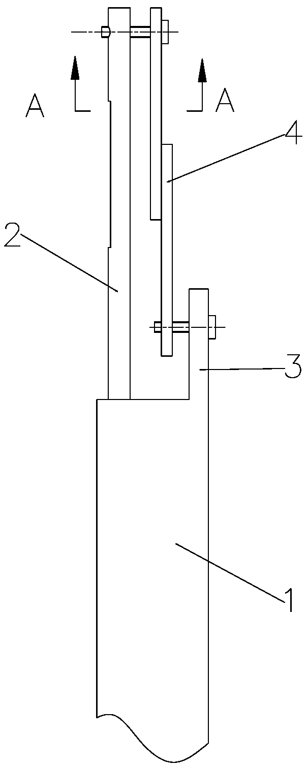
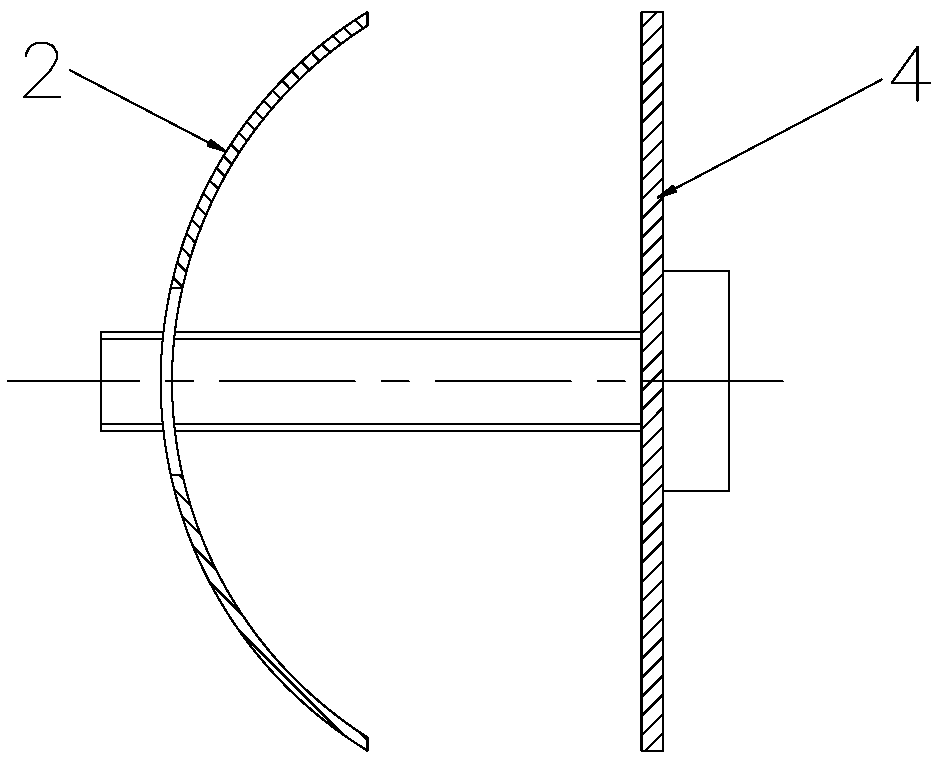
[0029] Such as image 3 Shown is a schematic structural diagram of the fusible rod embodiment 1 of the present invention. The fusible rod of this embodiment includes a fuse seat 1, a core rod slidingly fitted inside the fuse seat 1, a heat-gathering member 5 is provided at one end of the core rod, and a heat-gathering member 5 is provided on the fuse seat 1 corresponding to the heat-gathering member 5 The connecting piece 3 is provided with a fusible part 6 between the connecting piece 3 and the heat collecting part 5 , and the two ends of the fusible part 6 are respectively connected with the heat collecting part 5 and the connecting piece 3 . A heat collecting cavity 7 is provided between the heat collecting part 5 and the fusible part 6 in this embodiment, the width of the heat collecting part 5 is greater than the width of the fusible part 6, and the two sides of the heat collecting part 5 are connected with the fusible part 6 respectively. A heat-gathering gap 8 for dire...

Embodiment 2

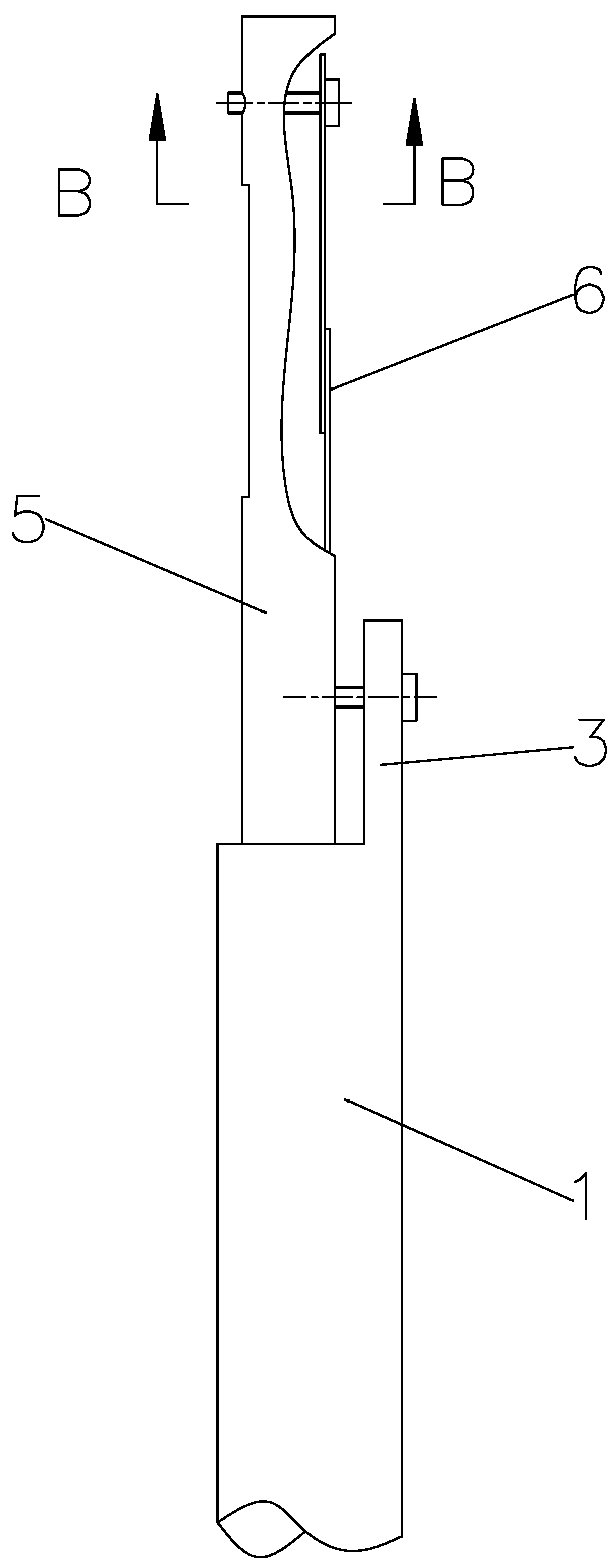
[0034] Such as Figure 5 Shown is a schematic structural diagram of the fusible rod embodiment 2 of the present invention. The fusible rod of this embodiment includes a fuse seat 1, a core rod slidingly fitted inside the fuse seat 1, a heat-gathering member 5 is provided at one end of the core rod, and a heat-gathering member 5 is provided on the fuse seat 1 corresponding to the heat-gathering member 5 The connecting piece 3 is provided with a fusible part 6 between the connecting piece 3 and the heat collecting part 5 , and the two ends of the fusible part 6 are respectively connected with the heat collecting part 5 and the connecting piece 3 . A heat collecting cavity 7 is provided between the heat collecting part 5 and the fusible part 6 in this embodiment, the width of the heat collecting part 5 is greater than the width of the fusible part 6, and the two sides of the heat collecting part 5 are connected with the fusible part 6 respectively. There is a heat-gathering gap ...

Embodiment 3

[0039] Such as Figure 6Shown is a schematic structural diagram of the fusible rod embodiment 2 of the present invention. The fusible rod of this embodiment includes a fuse seat 1, a core rod slidingly fitted inside the fuse seat 1, a heat-gathering member 5 is provided at one end of the core rod, and a heat-gathering member 5 is provided on the fuse seat 1 corresponding to the heat-gathering member 5 The connecting piece 3 is provided with a fusible part 6 between the connecting piece 3 and the heat collecting part 5 , and the two ends of the fusible part 6 are respectively connected with the heat collecting part 5 and the connecting piece 3 . A heat collecting cavity 7 is provided between the heat collecting part 5 and the fusible part 6 in this embodiment, the width of the heat collecting part 5 is greater than the width of the fusible part 6, and the two sides of the heat collecting part 5 are connected with the fusible part 6 respectively. There is a heat-gathering gap 8...


PUM


Abstract

The invention discloses a fusible rod. The fusible rod comprises a fusing seat; a mandrel is arranged in the fusing seat in a sleeving manner; a heat gathering piece is arranged at one end of the mandrel; a connecting sheet is arranged on the fusing seat; a fusible piece is arranged between the connecting sheet and the heat gathering piece; the two ends of the fusible piece are respectively connected with the heat gathering piece and the connecting sheet; a heat gathering cavity is formed between the heat gathering piece and the fusible piece; the width of the heat gathering piece is greater than that of the fusible piece; a heat gathering gap used for guiding air flow into the heat gathering cavity is formed between each of the two sides of the heat gathering piece and the fusible piece; an air outlet guide hole is also formed in the heat gathering piece. The air flow can be guided into the heat gathering cavity by arranging the heat gathering piece, setting the width of the heat gathering piece to be greater than that of the fusible piece, and meanwhile, and forming the heat gathering gap between each of the two sides of the heat gathering piece and the fusible piece; the air flow in the heat gathering cavity can heat the back surface of the fusible piece, so that the front surface, serving as a windward side, of the fusible piece and the back surface, serving as a leeside, of the fusible piece can be heated quickly, and the temperature can be risen quickly and is kept consistent with the temperature in a passage pipeline; therefore, the fusible rod can be fused in time.

Description

technical field [0001] The invention relates to a fusible protector, in particular to a fusible rod. Background technique [0002] Such as figure 1 Shown is a schematic structural diagram of an existing fusible rod. The fusible rod includes a fuse seat 1, a core rod slidingly fitted inside the fuse seat 1, a support plate 2 is provided at one end of the core rod, and the fuse seat 1 corresponds to the support plate 2 A connecting piece 3 is provided, and a fusible piece 4 is arranged between the supporting plate 2 and the connecting piece 3, and the two ends of the fusible piece 4 are respectively connected with the supporting plate 2 and the connecting piece 3 by screws. The other end of the core rod protrudes out of the fuse seat and is sleeved with a nut that is threadedly connected with the fuse seat 1, and the fuse seat 1 is provided with a nut that is sleeved on the core rod and is used to drive the core rod toward the position of the support plate. end moving sprin...

Claims


Application Information

Patent Timeline
Patent Type & Authority Patents(China)
IPC IPC(8): F16K17/38F16K17/40
CPCF16K17/383F16K17/406
Inventor 韩宏明
Owner CHONGQING SHUANGJIANG FIRE FIGHTING VENTILATION EQUIP MFG INSTALLATION
Features
  • R&D
  • Intellectual Property
  • Life Sciences
  • Materials
  • Tech Scout
  • Unparalleled Data Quality
  • Higher Quality Content
  • 60% Fewer Hallucinations
Learn More