
Roof lighting and refracting system

A technology of light and reflectors, which is applied in the field of roof lighting and refraction systems, can solve problems such as poor lighting effects and uneven lighting, and achieve the effects of reducing energy consumption of artificial lighting, uniform natural lighting, and uniform and soft light

Inactive Publication Date: 2016-12-21
JIANKE CONSTRUCTINO DESIGN INST SHANGHAI +1
View PDF4 Cites 1 Cited by
  • Summary
  • Abstract
  • Description
  • Claims
  • Application Information

AI Technical Summary

Problems solved by technology

[0004] The technical problem to be solved by the present invention is that some existing buildings with a patio in the middle adopt a roof lighting and refraction scheme, the lighting is not uniform, and the lighting effect is still not good

Method used


Image

  • Roof lighting and refracting system
  • Roof lighting and refracting system
  • Roof lighting and refracting system

Examples


Embodiment Construction

[0021] The present invention will be further described below in conjunction with the accompanying drawings and specific embodiments.

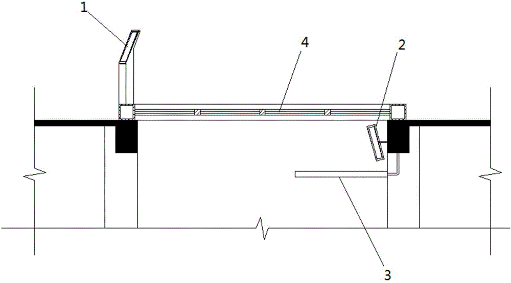
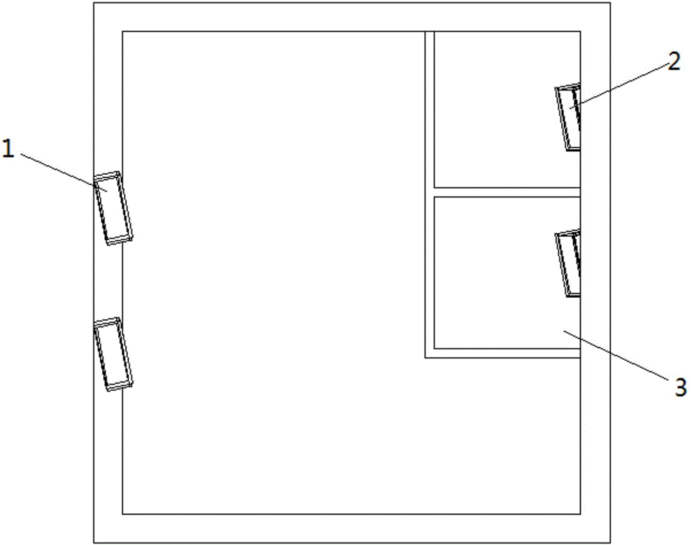
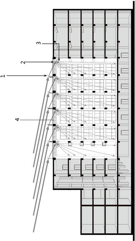
[0022] see Figure 1-Figure 3 , a roof lighting refraction system, the roof of a building with a patio in the middle is horizontally provided with a light-transmitting support structure 4, and a plurality of groups of lighting refraction units are arranged at vertical and horizontal intervals on the support structure 4; the lighting refraction unit includes a lighting lens 1. The lighting lens 1 refracts the light to increase the incident angle of the light. The lighting lens 1 is equipped with a first photoelectric sensor and a first rotating mechanism, and the first photoelectric sensor controls the rotating mechanism to rotate to a suitable lighting angle according to the incident direction of the light; The lighting refraction unit also includes a reflector 2 located below the support structure 4 corresponding to the position of the lightin...


PUM


Abstract

The invention relates to a roof lighting and refracting system. A light-transmitting supporting structure is horizontally arranged on the roof of a building with a courtyard in the middle. Multiple sets of lighting and refracting units are longitudinally, transversely and evenly arranged on the supporting structure at intervals. Each lighting and refracting unit comprises a lighting lens. The light ray entry angle is increased after light rays are refracted through the lighting lenses. Each lighting lens is provided with a first photoelectric sensor and a first rotation mechanism. The first photoelectric sensors control the rotation mechanisms to rotate to the appropriate lighting angle according to the light ray entry direction. Each lighting and refracting unit further comprises a reflector located below the supporting structure and corresponding to the corresponding lighting lens in position. The reflectors receive the light rays refracted by the lighting lenses and reflect the light rays downwards to diffusion scattering mirrors located below the reflectors. The diffusion scattering mirrors evenly scatter the light rays in the direction of the courtyard on the inclined lower portion. Each reflector is provided with a second photoelectric sensor and a second rotation mechanism. The second photoelectric sensors control the second rotation mechanisms to rotate to the appropriate lighting angle according to the light ray entry direction.

Description

technical field [0001] The invention relates to a roof lighting refraction system, which belongs to the technical field of building lighting. Background technique [0002] Due to the limitation of the sun's altitude angle and azimuth angle, sunlight can only directly shine into the deep vertical patio and atrium floor in a certain period of time, so the light illuminance in the area fluctuates greatly during the day; on the other hand, direct light is easy to Cause visual damage, and cause light confusion in the area, affecting the use of space. [0003] At present, there are many buildings with large depths. There are patios in the middle of the buildings. The lighting effect in the patios is poor, which reduces the comfort of people's lives and offices. Uneven, the lighting effect is still not good. Contents of the invention [0004] The technical problem to be solved by the present invention is that some existing buildings with a patio in the middle adopt a roof light...

Claims


Application Information

Patent Timeline
IPC IPC(8): F21S11/00
CPCF21S11/002F21S11/005F21S11/007
Inventor 王丹蔡廷龙王龙梁晓丹
Owner JIANKE CONSTRUCTINO DESIGN INST SHANGHAI
Learn More