Multiple-light source scanning detection method

A technology of scanning detection and multi-light source, which is applied in the field of scanning detection, can solve the problems of repeated scanning, error between design moving speed and actual moving speed, etc., and achieve the effect of improving scanning speed, avoiding positioning error and good stability

Inactive Publication Date: 2016-12-21
中国科学院嘉兴微电子仪器与设备工程中心
View PDF7 Cites 3 Cited by
  • Summary
  • Abstract
  • Description
  • Claims
  • Application Information

AI Technical Summary

Problems solved by technology

[0004] The existing technology only detects a certain point on the sample to be tested at the same time, and there is an acceleration and deceleration process of changing direction in the fast scan, resulting in an error between the design moving speed and the actual moving speed, and there is a problem of repeated scanning

Method used


Image

  • Multiple-light source scanning detection method
  • Multiple-light source scanning detection method
  • Multiple-light source scanning detection method

Examples


Embodiment 1

[0026] This embodiment provides a scanning detection method with multiple light sources, and the surface of the sample stage is distributed circularly.

[0027] There are two light sources, and the two light sources are arranged linearly and coincide with the radius of the sample stage.

[0028] The sample stage rotates around its center at a constant angular velocity.

[0029] While the sample stage rotates at the constant angular velocity, the sample stage translates at a constant linear velocity along the arrangement direction of the light sources.

[0030] In the embodiment of the present application, the movement is realized by means of uniform rotation of the sample stage and uniform translation in one direction, which avoids the time-consuming process of acceleration and deceleration of the sample stage, and avoids positioning errors caused by unstable speed changes of the sample stage during the scanning process. Effectively improve scanning speed and positioning accu...

Embodiment 2

[0032] like figure 1 As shown, this embodiment provides a multi-light source scanning detection method, which uses vacuum to adsorb the sample to the surface of the sample stage.

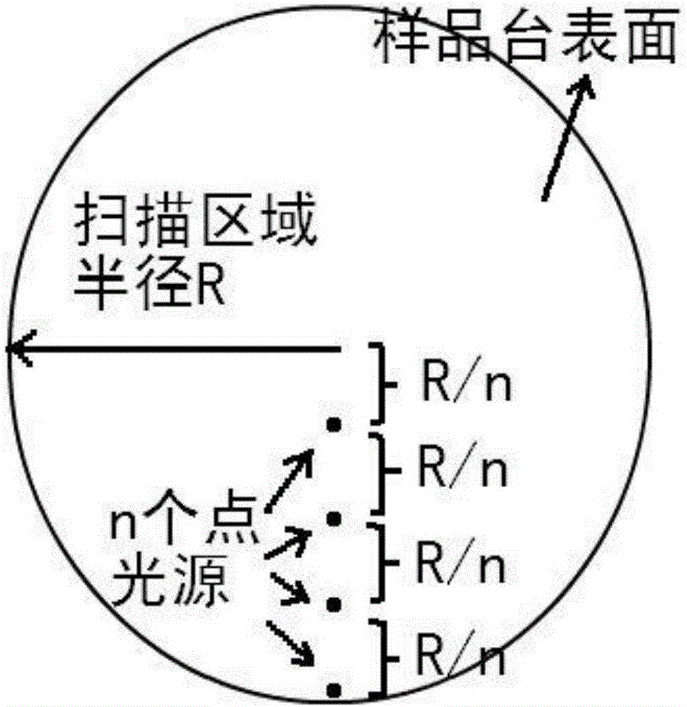
[0033] The surface of the sample stage is distributed in a circle, and the radius of the sample stage is R.

[0034] The light source is n point light sources, and the n point light sources are arranged in a straight line along a radius of the sample stage at an equidistance R / n, n is an integer greater than 2, and the illumination position of the light source is fixed. Wherein, the lowermost light source among the n point light sources is located at the lowermost edge of the sample stage.

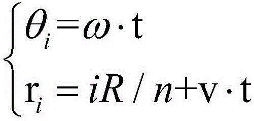
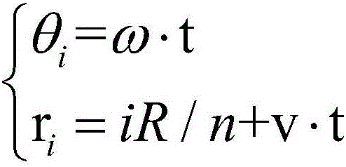
[0035] The sample stage rotates around its center at a constant angular velocity.

[0036] While the sample stage rotates at the constant angular velocity, the sample stage translates at a constant linear velocity along the arrangement direction of the light sources.

[0037] When the rotation speed of the sa...


PUM


Abstract

The invention belongs to the technical field of a scanning detection technology, and discloses a multiple-light source scanning detection method. The surface of a sample bench is distributed in a circle shape; the number of the light sources is two, the two light sources enable linear arrangement, and are superposed with radius of the sample bench; the sample bench rotates by surrounding a center of a circle at a constant angular velocity; when the sample bench rotates by surrounding the center of the circle at the constant angular velocity, the sample bench moves horizontally along the arrangement direction of the light sources at the constant linear velocity. The method increases the scanning efficiency and stability as well as increases the positioning precision.

Description

technical field [0001] The invention relates to the technical field of scanning detection, in particular to a multi-light source scanning detection method. Background technique [0002] Scanning detection is the most common detection method in optical detection. It refers to the detection of only a certain point on the sample to be tested at the same time, and the detection of the entire sample through the detection of different positions at different times, in which scanning points at different times The change is mainly achieved by moving the sample and the position of the illumination. [0003] In the scanning detection method, the detection speed not only depends on the test speed of a single point, but also factors such as scanning trajectory and moving speed become important factors affecting the detection speed. Improving the detection speed is mainly achieved from the following two aspects: 1. Improving the moving speed of the sample / illumination point; 2. Optimizin...

Claims


Application Information

Patent Timeline
Patent Type & Authority Applications(China)
IPC IPC(8): G01C11/02G01N21/86
CPCG01C11/025G01N21/86G01N2021/845
Inventor 陈鲁刘虹遥张朝前杨乐马砚忠路鑫超
Owner 中国科学院嘉兴微电子仪器与设备工程中心
Why Eureka
Try Eureka