
Dynamic bias LDO (low-dropout regulator) circuit

A bias circuit and dynamic technology, applied in the direction of adjusting electrical variables, control/regulating systems, instruments, etc., can solve the problem of insufficient transient response capability of LDO circuits, and achieve the effect of good transient response capability and stable output voltage

Inactive Publication Date: 2016-12-21
HUNAN UNIV OF ARTS & SCI
View PDF5 Cites 2 Cited by
  • Summary
  • Abstract
  • Description
  • Claims
  • Application Information

AI Technical Summary

Problems solved by technology

[0004] Based on the analysis of the existing LDO circuit, the purpose of the present invention is to provide a dynamic bias LDO circuit, aiming at solving the problem that the transient response capability of the existing LDO circuit is not high enough

Method used


Image

  • Dynamic bias LDO (low-dropout regulator) circuit
  • Dynamic bias LDO (low-dropout regulator) circuit

Examples


Embodiment Construction

[0018] In order to make the object, technical solution and advantages of the present invention clearer, the present invention will be further described in detail below in conjunction with the accompanying drawings and embodiments. It should be understood that the specific embodiments described here are only used to explain the present invention, not to limit the present invention.

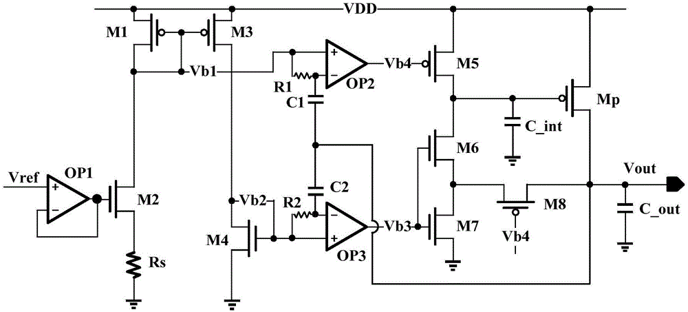
[0019] Such as figure 1 As shown, the embodiment of the present invention provides a dynamic bias LDO circuit, including a fixed bias circuit, a dynamic bias circuit, and a power tube grid terminal control circuit, wherein:

[0020] The fixed bias circuit includes: a reference voltage Vref, an amplifier OP1, transistors M1-M4, and a resistor Rs for generating fixed bias voltages Vb1 and Vb2;

[0021] The dynamic bias circuit includes: resistors R1, R2, capacitors C1, C2, amplifiers OP2, OP3, used to generate superimposed signals Vb3 and Vb4 of dynamic bias and fixed bias; Vb3 controls the gate vol...


PUM


Abstract

The invention provides a dynamic bias LDO (low-dropout regulator) circuit. Transient change of output voltage is sampled through coupling by capacitors, two dynamic bias signals are produced through comparison with fixed bias voltage and open or close a loop for charge and discharge of power tube grid end parasitic capacitors according to the change condition of the output voltage, then voltage of a power tube grid end is regulated, the output voltage is stabilized, and therefore, the circuit has good transient response capability.

Description

technical field [0001] The invention relates to the technical field of chip power management, in particular to a dynamic bias LDO circuit. Background technique [0002] With the rapid development of integrated circuits, power management modules are widely used in SoC chips with multiple voltage domains. As an important circuit of the power management module, LDO (Low-dropout Regulator) can be used to stabilize voltage output and supply power to multiple circuit modules. A typical LDO achieves fast load change response by adjusting the primary and secondary poles and zeros. To improve the transient response capability of the LDO, the method of increasing the loop bandwidth is usually adopted, which can improve the small-signal performance of the LDO in the low-medium frequency domain. In the case of large signal analysis, the typical method is to use a large off-chip coupling capacitor to reduce the output overshoot, or increase the bias current to obtain a high output chan...

Claims


Application Information

Patent Timeline
IPC IPC(8): G05F1/56
CPCG05F1/561
Inventor 丁一
Owner HUNAN UNIV OF ARTS & SCI
Features
  • Generate Ideas
  • Intellectual Property
  • Life Sciences
  • Materials
  • Tech Scout
  • Unparalleled Data Quality
  • Higher Quality Content
  • 60% Fewer Hallucinations
Learn More