Improved pulse sequence control method of switch power supply and device thereof
A pulse sequence, switching power supply technology, applied in the direction of conversion equipment without intermediate conversion to AC, can solve the problems of large output voltage steady-state error, unsuitable voltage accuracy, large output voltage ripple, etc., to achieve easy integration, good Transient Response Capability, Cost-Effective Effect
- Summary
- Abstract
- Description
- Claims
- Application Information
AI Technical Summary
Problems solved by technology
Method used
Image

Examples
Embodiment 1
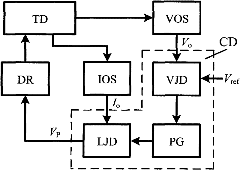
[0053] figure 1 It is shown that a specific embodiment of the present invention is a control method of a switching power supply, and its specific method is:
[0054] At the beginning of each switching cycle, according to the switching converter TD output voltage V o with reference voltage V ref The relationship between high and low, and the range of the load size, select the effective control pulse in the switching cycle, so as to realize the control of the switching converter TD. Its control pulse selection rule is: when the load current I o Higher than the load current threshold I 1 , if V o below V ref , using the control pulse P H,1 Control the switch tube S in the converter; if V o higher than V ref , using the control pulse P L,1 Control switch tube. When the load current I o At the load current threshold I 1 and I 2 between, if V o below V ref , using the control pulse P H,2 Control switch tube; if V o higher than V ref , using the control pulse P L,2...
Embodiment 2
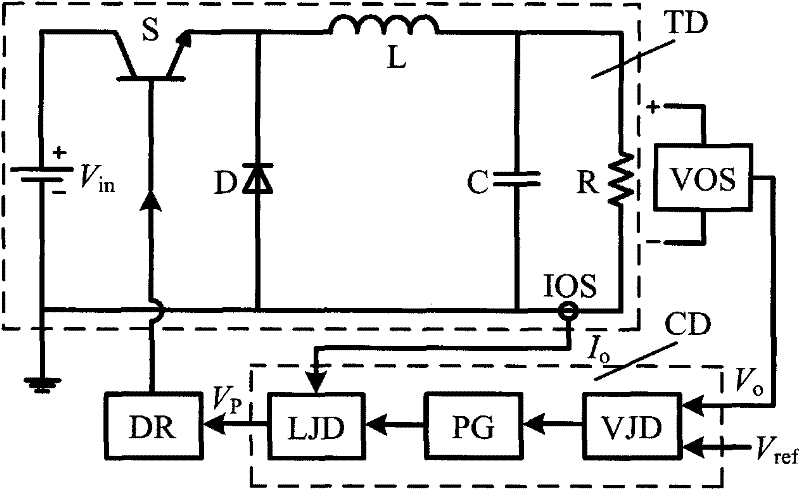
[0073] Figure 10 As shown, this example is basically the same as the first example, the difference is: the control pulse P is generatedH,n The method is: at the beginning of a certain switching cycle t 0 moment, the control pulse P H,n From low level to high level, the switch tube S in the converter TD is turned on, and the inductor current I L rise; when I L rises to the peak value of the inductor current I H,n , the control pulse P H,n From high level to low level, the switch tube S is turned off until the end of the switching period t 0 +T. Generate control pulse P L,n The process and produce P H,n The process is similar, the difference is that the peak value of the inductor current corresponding to the control pulse is I L,n . It can be seen that the control pulse P H,n and P L,n (n=1, 2, 3...N+1) respectively correspond to the fixed inductor current peak value I H,n and I L,n (I H,n >I H,2 ≥I L,1 >I H,3 ≥I L,2 ...>I H,N+1 ≥I L,N >I L,N+1 ).
[0074]...
Embodiment 3
[0076] Figure 11 As shown, this example is basically the same as the first example, the difference is: the control pulse P is generated H,n The method is: at the beginning of a certain switching cycle t 0 moment, the control pulse P H,n From low level to high level, the switch tube S in the converter TD is turned on, and the voltage V on the equivalent series resistance (ESR) of the filter capacitor ESR rising; when V ESR Rise to the peak equivalent series resistance voltage V H,n , the control pulse P H,n From high level to low level, the switch tube S is turned off until the end of the switching period t 0 +T. Generate control pulse P L,n The process and produce P H,n The process is similar, the difference is that the peak value of the equivalent series resistance voltage corresponding to the control pulse is V L,n . It can be seen that the control pulse P H,n and P L,n (n=1, 2, 3...N+1) respectively correspond to the fixed equivalent series resistance voltage p...
PUM
 Abstract
Description
Claims
Application Information