A kind of PCCM Boost converter control method and its device

A converter control and controller technology, which is applied in the output power conversion device, control/regulation system, DC power input conversion to DC power output and other directions, can solve the problem of large converter ripple, and achieve the output voltage ripple Small, improve the transient response speed, enhance the effect of system stability

Active Publication Date: 2021-01-29
SOUTHWEST JIAOTONG UNIV
View PDF9 Cites 0 Cited by
  • Summary
  • Abstract
  • Description
  • Claims
  • Application Information

AI Technical Summary

Problems solved by technology

[0006] In order to solve the problem of large ripple in the voltage-type PT control PCCM Boost converter, and improve the transient performance and steady-state performance of the Boost converter at the same time

Method used


Image

  • A kind of PCCM Boost converter control method and its device
  • A kind of PCCM Boost converter control method and its device
  • A kind of PCCM Boost converter control method and its device

Examples


Embodiment Construction

[0037] The present invention will be further described below in conjunction with the accompanying drawings and specific embodiments.

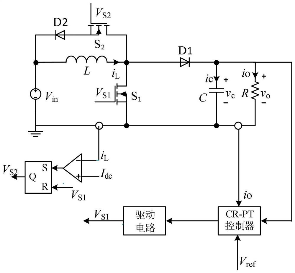
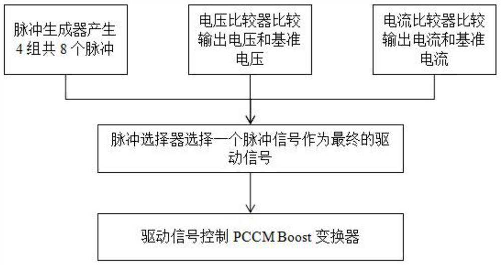
[0038] A kind of PCCM Boost converter control method of the present invention, its circuit structure is as follows figure 1 As shown, the specific control logic is as follows figure 2 shown, including the following steps:

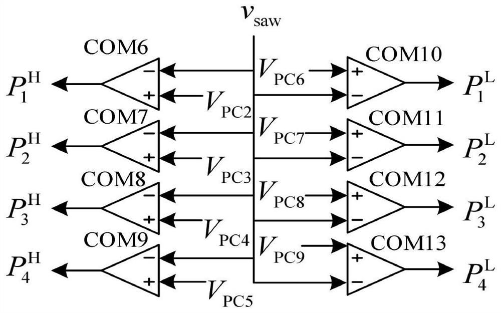
[0039] 1. Pulse generator of CR-PT controller (such as image 3 shown) to generate four groups of pulses with different frequencies {P j}, j=1, 2, 3, 4, and each group includes two pulses with the same frequency but different duty ratios, that is, a high duty ratio P j H and low duty cycle P j L , where j = 1, 2, 3, 4 for selection by the pulse picker.

[0040] 2. At the beginning of any switching period of the PCCM Boost converter, the output voltage v of the switching power supply is o Feedback to the voltage comparator of the CR-PT controller (as Figure 4 shown), and the reference voltage value V ref Compared;...


PUM


Abstract

The invention discloses a PCCM Boost converter control method and its device. The controller includes a pulse generator, a voltage comparator, a current comparator and a pulse selector; the pulse generator generates four sets of pulses with the same frequency and different duty ratios. For the selection of the pulse selector, the voltage comparator compares the output voltage with the reference voltage, the current comparator compares the output current with the reference current, and the output signals of the pulse generator, voltage comparator, and current comparator are used as the input of the pulse selector The signal is thus selected as the pulse to drive the PCCM Boost converter to realize the control of the converter. The application of the invention makes the output voltage ripple of the PCCM Boost converter smaller, and at the same time improves the transient performance and steady-state performance of the converter.

Description

technical field [0001] The invention belongs to the field of power electronic control, and in particular relates to a PCCM Boost converter control method and a device thereof. Background technique [0002] With the rapid development of power electronic devices and power electronic control technology, switching power supply technology has become a research hotspot and important application of power electronics technology. Switching power supply technology uses switching converters and corresponding controls to realize the conversion of electric energy to meet the power requirements of various power consumption occasions. Switching power supply technology has the advantages of high efficiency, high power density, and small size, and is widely used in the fields of computers, communication equipment, aerospace, new energy, and LED lighting. The switching power supply is mainly composed of two parts: the main power circuit and the control circuit. The power main circuit includ...

Claims


Application Information

Patent Timeline
Patent Type & Authority Patents(China)
IPC IPC(8): H02M3/158
CPCH02M3/1584
Inventor 杨平范文彭宇圣李欣洋
Owner SOUTHWEST JIAOTONG UNIV
Why Eureka
Try Eureka