
A method for real-time measurement of carbon emissions in a power system and a carbon meter system

A carbon emission and power system technology, applied in the field of real-time carbon emission measurement, method and carbon meter system in the power system, can solve the problem that real-time carbon emission measurement cannot be realized, carbon emission cannot be displayed intuitively, and it is not conducive to real-time carbon emission of power users. And other issues

Active Publication Date: 2020-04-17
TSINGHUA UNIV
View PDF4 Cites 0 Cited by
  • Summary
  • Abstract
  • Description
  • Claims
  • Application Information

AI Technical Summary

Problems solved by technology

The existing macro-statistical method attributes all carbon emissions to the power plant level, which cannot reflect the network characteristics of the power system and ignores the flow and distribution of carbon emissions from "source" to "exit".
Moreover, it is impossible to realize real-time measurement of carbon emissions, and it is also impossible to intuitively display the carbon emissions caused by users' electricity consumption.
Therefore, it is not conducive to power users to respond to real-time carbon emissions, and to reduce carbon emissions by adopting low-carbon electricity consumption measures

Method used


Image

  • A method for real-time measurement of carbon emissions in a power system and a carbon meter system
  • A method for real-time measurement of carbon emissions in a power system and a carbon meter system
  • A method for real-time measurement of carbon emissions in a power system and a carbon meter system

Examples


Embodiment Construction

[0053] A method for real-time measurement of carbon emissions in a power system and a carbon meter system proposed by the present invention will be further described in detail below in conjunction with the accompanying drawings and specific embodiments.

[0054] A method for real-time measurement of carbon emissions in a power system proposed by the present invention, the method specifically includes the following steps:

[0055] 1) Determine the basic indicators of the carbon emission flow of the power system;

[0056] The basic indicators of power system carbon emission flow include node carbon potential, carbon flow rate, carbon flow and branch carbon flow density. The specific definitions of each indicator are as follows:

[0057] 1-1) Node carbon potential: the carbon emissions on the power generation side caused by the generation or transmission of unit electric energy at the node, the unit is kgCO 2 / kWh; node carbon potential needs to be obtained through the calculati...


PUM


Abstract

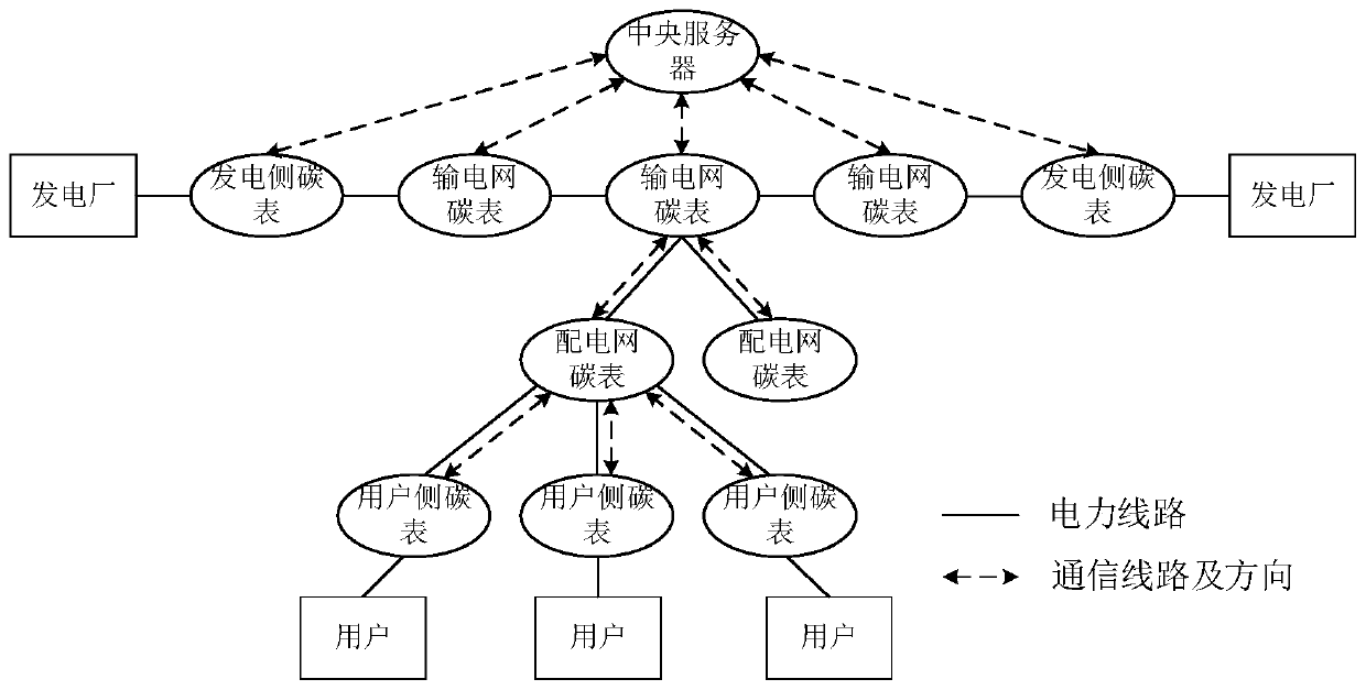
The present disclosure provides a system for measuring carbon emissions in a power system. The system includes: generation carbon meters, distributed respectively in generators in the power system; network carbon meters, distributed respectively in nodes in the power system; consumption carbon meters, distributed respectively in consumers in the power system; and a center server, in which each carbon meter is configured to collect data for measuring the carbon emissions. The center server is configured to acquire the collected data and to measure the carbon emissions according to the acquired data, and to send measuring results to the corresponding carbon meter. Then each carbon meter is further configured to display according to the measuring results. The carbon emission may be measured in real time.

Description

technical field [0001] The invention belongs to the low-carbon technical field of power systems, and in particular relates to a method for real-time measurement of carbon emissions in a power system and a carbon meter system. [0002] technical background [0003] Issues such as the energy crisis and global climate change have aroused people's increasing concern. Reducing the excessive consumption of fossil fuels and realizing low-carbon development has become the common goal of all industries in all countries. As an important part of energy supply, the power industry is also a major industry that consumes fossil fuels, resulting in a large amount of carbon emissions. Since my country's power source structure is dominated by coal-fired thermal power, this phenomenon is particularly significant in my country. According to statistics, in recent years, the carbon dioxide emitted by my country's power industry accounts for about half of the country's carbon emissions caused by ...

Claims


Application Information

Patent Timeline
Patent Type & Authority Patents(China)
IPC IPC(8): G06Q10/06G06Q50/06
CPCG06Q10/063G06Q50/06G01N33/004G01N33/0062G06Q10/06Y02E40/70Y02P90/82Y02P90/84Y04S10/50
Inventor 康重庆程耀华孙彦龙
Owner TSINGHUA UNIV
Features
  • Generate Ideas
  • Intellectual Property
  • Life Sciences
  • Materials
  • Tech Scout
  • Unparalleled Data Quality
  • Higher Quality Content
  • 60% Fewer Hallucinations
Learn More