Card reader and card lock mechanism

A locking mechanism and card reader technology, applied in the field of card readers, can solve the problems of deformation of the connecting handle, shaking of the locking handle and the connecting handle of the connecting handle and the fan-shaped gear, etc., and achieve the effect of preventing the card from being disengaged

Active Publication Date: 2016-12-21
NIDEC SANKYO CORP
View PDF6 Cites 5 Cited by
  • Summary
  • Abstract
  • Description
  • Claims
  • Application Information

AI Technical Summary

Problems solved by technology

[0006] In the card reader described in Patent Document 1, since the locking handle and the sector gear are connected through the connecting handle, there is a hidden danger that the connecting part between the locking handle and the connecting handle and the connecting part between the connecting handle and the sector gear shake.
Also, since the connecting handle is formed in a flat plate shape, if a large load is applied to the connecting handle, there is a possibility that the connecting handle may be deformed
According to the research of the inventors of the present application, in the card reader described in Patent Document 1, if the connecting part of the locking handle and the connecting handle and the connecting part of the connecting handle and the sector gear shake and the connecting handle deforms, there are obviously the following hidden dangers : Although the motor is stopped, the locking tooth is disengaged from the card in a state where it is in contact with the locking tooth and extraction is prevented, and the card is pulled out

Method used


Image

  • Card reader and card lock mechanism
  • Card reader and card lock mechanism
  • Card reader and card lock mechanism

Examples


Embodiment approach 1

[0072] (Schematic structure of the card reader)

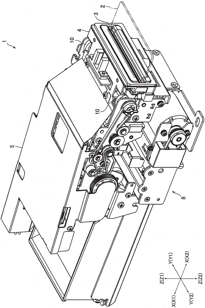
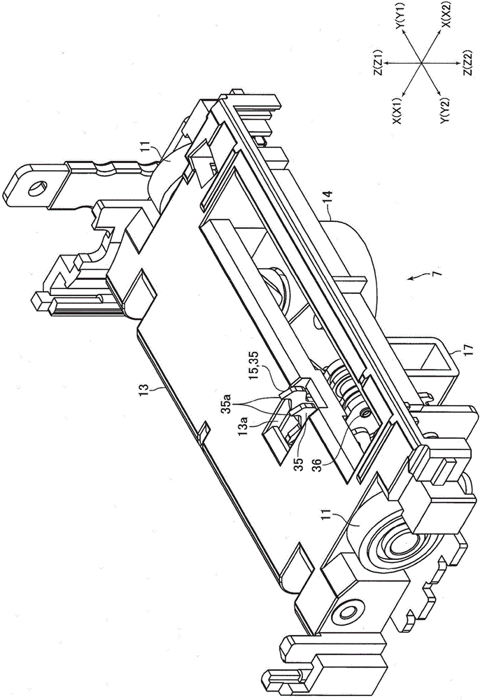
[0073] figure 1 It is a perspective view of the card reader 1 concerning Embodiment 1 of this invention. figure 2 yes figure 1 It is a perspective view of the portion below the card conveyance path of the shown card insertion section 4 .

[0074] The card reader 1 in this embodiment is a device for reading magnetic data recorded on the card 2 and / or recording magnetic data on the card 2, and is installed in an ATM (Automated Teller Machine: Automated Teller Machine) or the like. It is used for the specified host device. The card reader 1 has a card insertion part 4 and a main body part 5, wherein the card insertion part 4 is formed with a card insertion port 3 through which a card 2 is inserted and ejected. A card conveyance path for conveying the card 2 inserted through the card insertion opening 3 is formed inside the card reader 1 . In addition, the card reader 1 has a card lock mechanism 7 that prevents the card from ...

Embodiment approach 2

[0103] The card reader 51 in this embodiment is the same as the card reader 1 in Embodiment 1, and is a device for reading magnetic data recorded on the card 2 and / or recording magnetic data to the card 2, and is equipped with It is installed in designated host devices such as ATMs and used. The structure of this card reader 51 will be described below. In addition, below, the same code|symbol is attached|subjected to the same or common structure as Embodiment 1, and the description is abbreviate|omitted or simplified.

[0104] (Schematic structure of the card reader)

[0105] Image 6It is a schematic plan view of the card reader 51 concerning Embodiment 2 of this invention. Figure 7 yes Image 6 A side view of the card locking mechanism 57 is shown.

[0106] Like the card reader 1 in Embodiment 1, the card insertion port 3 through which the card 2 is inserted and ejected is formed in the card reader 51 . In addition, a card conveyance path for conveying the card 2 inse...


PUM

PropertyMeasurementUnit
Thicknessaaaaaaaaaa
Thicknessaaaaaaaaaa

Abstract

Disclosed is a card reader and a card lock mechanism which are capable of preventing a prevention pawl for preventing drawing of a card from disengaging from a card in a state that drawing is prevented by the prevention pawl contacted with the card. In the card reader, a card lock mechanism (7) is structured to prevent drawing of the card from a card insertion port when the card is clogged in a card conveying passage. The card lock mechanism (7) includes a motor (14), a lock member (15) which is configured with prevention pawls (35a) contacted with a card and preventing drawing of the card and which is movable between a contact position where the prevention pawls (35a) are contacted with the card and a retreated position where the prevention pawls (35a) are retreated from the card conveying passage, and a power transmission mechanism (16) for transferring power of the motor (14) to the lock member (15). The power transmission mechanism (16) is configured with a final gear (25) arranged at a place closest to a lock member (15) side in a power transmission direction from the motor (14) to the lock member (15), and the lock member (15) is configured with a sector gear (35b) engaging with the final gear (25).

Description

technical field [0001] The present invention relates to a card reader for reading data recorded on a card or recording data to a card. Furthermore, the present invention relates to a card locking mechanism installed and used in the card reader. Background technique [0002] Conventionally, a card reader for reading data recorded on a card or recording data to a card has been widely used. In industries such as financial institutions that use card readers, criminals intentionally jam cards in card readers to illegally obtain cards, so-called phishing fraud, which is a major problem. Therefore, conventionally, a card reader having a card lock mechanism for preventing phishing fraud has been proposed (for example, refer to Patent Document 1). [0003] In the card reader described in Patent Document 1, the card lock mechanism has a lock lever that prevents the card from being pulled out of the card insertion slot. The locking handle has a substantially triangular-shaped lockin...

Claims


Application Information

Patent Timeline
IPC IPC(8): G07D11/00
CPCG06K13/0862G06K7/0056G06K7/082G06K2207/1016G07D11/14
Inventor 桑木博史武田浩重宫泽伸也
Owner NIDEC SANKYO CORP
Why Eureka
Try Eureka