Pay-off mechanism for cabling machine

A cable forming machine and cable technology, which is applied in the direction of cable/conductor manufacturing, circuits, electrical components, etc., can solve the problems of low cable forming efficiency, low cable quality, and difficulty in meeting market demand.

Inactive Publication Date: 2016-12-21
CHAOHU JINYE ELECTRIC MACHINERY
View PDF5 Cites 2 Cited by
  • Summary
  • Abstract
  • Description
  • Claims
  • Application Information

AI Technical Summary

Problems solved by technology

However, the cable forming efficiency of the existing cable forming machine is low, and the quality of the formed cable is not high, so it is difficult to meet the demand of the market

Method used


Image

  • Pay-off mechanism for cabling machine
  • Pay-off mechanism for cabling machine

Examples


Embodiment Construction

[0015] In order to make the purpose, technical solutions and advantages of the embodiments of the present invention clearer, the technical solutions in the embodiments of the present invention will be clearly and completely described below in conjunction with the drawings in the embodiments of the present invention. Obviously, the described embodiments It is a part of embodiments of the present invention, but not all embodiments. Based on the embodiments of the present invention, all other embodiments obtained by persons of ordinary skill in the art without creative efforts fall within the protection scope of the present invention.

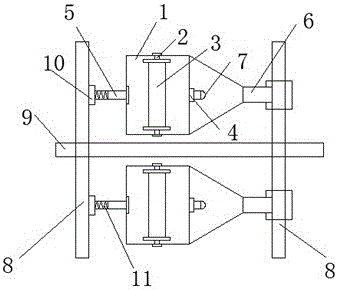
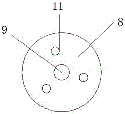
[0016] combined with figure 1 with figure 2 , a pay-off mechanism of a cable cabling machine, comprising a pay-off frame, the pay-off frame comprising a pay-off frame 1, a rotating shaft 2 is provided in the front and rear of the pay-off frame 1, and a pay-off frame is arranged on the rotating shaft 2 Roller 3, the middle part of the pay-off fr...


PUM


Abstract

The invention provides a pay-off mechanism for a cabling machine, and relates to the field of cabling machine equipment. The pay-off mechanism comprises a pay-off rack, the pay-off rack comprises pay-off frames, rotating shafts are arranged on front and back sides in each pay-off frame, pay-off rollers are arranged on the rotating shafts, a connecting rod is arranged at the middle of each pay-off frame, a through hole is formed in each connecting rod, a left connecting shaft is arranged at a left end of each pay-off frame, a right connecting shaft is arranged at a right end of each pay-off frame, and the right connecting shaft is a hollow shaft. The pay-off mechanism provided by the invention is reasonable in structural design and is stable in pay-off.

Description

technical field [0001] The invention relates to the field of cable forming machine equipment, in particular to a wire-releasing mechanism of a cable forming machine. Background technique [0002] The process of twisting multiple wires according to the pitch required by the process to form a bundle or strand is called cabling, and the equipment that realizes this process is usually called a cabling machine. The cable forming machine is generally equipped by wire and cable manufacturers. Among them, the cable forming machine is divided into a winch type cable forming machine and a cage type cable forming machine. The stranding part of the cage type cable forming machine is installed by one or several Auger composition. However, the cable forming efficiency of the existing cable forming machines is low, and the quality of the formed cables is not high, so it is difficult to meet the demands of the market. Contents of the invention [0003] Aiming at the deficiencies of the ...

Claims


Application Information

Patent Timeline
Patent Type & Authority Applications(China)
IPC IPC(8): H01B13/00H01B13/02
CPCH01B13/0207H01B13/0036
Inventor 黄世来
Owner CHAOHU JINYE ELECTRIC MACHINERY
Why Eureka
Try Eureka